MODULE 1. Heat Pump Technology
February 5, 2026Lesson 2. The Vapour Compression Cycle
February 9, 2026[gspeech-button]
Welcome to this lesson! Start by watching a recap video of this lesson.
Click on the gear icon to choose subtitles of your preferred language.
1.1 Concept of heat pump
The general concept of heat pump can be clearly understood by analogy with hydraulic systems, as illustrated in Figure 1‑1.
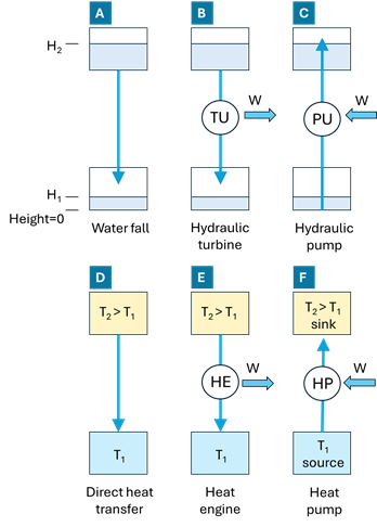
Figure 1‑1. Analogy between hydraulic and thermal systems.
In the hydraulic domain, case A represents a natural process: water flows spontaneously from a higher elevation to a lower elevation due to gravity. This flow requires no external energy input and is analogous to heat conduction (case D), where heat flows naturally from a higher temperature to a lower temperature
. In both cases, the driving force is a gradient (height difference or temperature difference), and the process is irreversible and dissipative.
Case B introduces a machine that extracts useful work from the natural flow. In the hydraulic system, a turbine (TU) converts the potential energy of falling water into mechanical work (W). Its thermal equivalent is a heat engine (HE, case E), which extracts work from a heat flow between a hot source at and a cold sink at
. A typical example of a heat engine is an internal combustion engine, which converts heat released by fuel combustion into mechanical work by operating between a high-temperature combustion chamber and a lower-temperature exhaust. In both cases B and E, useful work is produced while the natural direction of flow (downward for water, hot to cold for heat) is preserved.
Cases C and F represent the inverse processes. In hydraulics, a pump (PU) consumes mechanical work to move water from a lower elevation to a higher one, against the natural direction imposed by gravity. The thermal analogue is the heat pump (HP, case F), which consumes work to move heat from a low-temperature source to a high-temperature sink
, against the natural direction of heat flow. Just as a hydraulic pump does not create water but relocates it to a higher potential level, a heat pump does not generate heat but transfers existing thermal energy to a higher temperature level, using work input.
This analogy highlights the fundamental role of the heat pump: using work to upgrade energy quality, enabling heat transfer from cold to hot in the same way a hydraulic pump lifts water to a higher elevation.
Note the difference between a fossil-fuel boiler and a heat pump:
- A boiler generates heat by burning fuel for heating water, which is then distributed for space heating or domestic hot water (DHW) in the building. It operates by converting chemical energy into thermal energy directly.
- In contrast, a heat pump moves thermal energy from one place to another, typically extracting heat from the air, water, or ground and transferring it to the building. It requires electrical energy to operate but is much more energy-efficient than a boiler, as it transfers more heat than the electrical energy it consumes.
While a boiler directly generates heat, a heat pump upgrades the available thermal energy, making it a more sustainable choice for heating, especially in moderate climates.
1.2 Types of heat pumps
The process of transferring heat against its natural direction requires activation energy (W in Figure 1‑1), which can come in various forms depending on the heat pump technology.
Mechanical Compression Heat Pump: This is by far the most common type of heat pump and the topic of this course. It uses mechanical energy to compress and circulate the working fluid (refrigerant) through a closed cycle that transports heat between the source (where it absorbs thermal energy at a low temperature) and the sink (where it releases thermal energy at a high temperature), see Figure 1‑2. Think of the refrigerant circuit as a conveyor belt, continuously transporting thermal energy from one place to another.

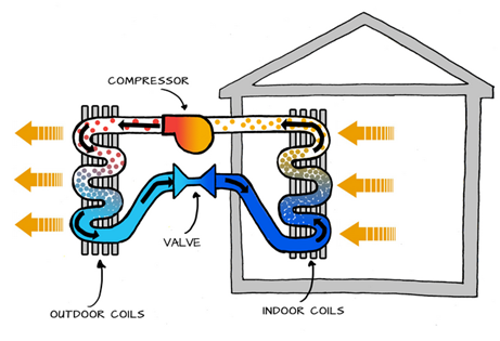
Figure 1‑2. Basic operation of a mechanical compression heat pump (left side: heating the house, right side: cooling the house)
The mechanical energy that drives the compressor typically comes from an electric motor in electric heat pumps. However, there are also heat pumps that use a gas engine to generate the required mechanical power to drive the compressor.
Absorption Heat Pumps: They use thermal energy rather than mechanical work for activation. In these systems, heat from a fuel source (such as natural gas, waste heat, solar thermal, etc.) is used to absorb the refrigerant into a liquid. This process allows the refrigerant to be released and transfer heat to the sink. The activation temperature must always be higher than the sink temperature to enable the transfer of heat. Absorption heat pumps are typically used in large-scale systems or in applications where waste heat is readily available, making them suitable for industrial or special commercial settings where low-cost thermal energy is abundant. They are not common in the residential sector.
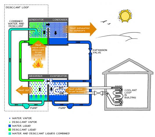
Figure 1‑3. An absorption chiller’s dual cycle. Source: Sustainability Workshop, Venture Well
Another small-scale option is the Peltier heat pump, which uses electrical energy to create a temperature difference through the Peltier effect. This effect causes heat to move from one side of the device to the other when an electric current is passed through two different conductors (Figure 1‑4). Peltier heat pumps are commonly used for cooling small devices like electronics but are less effective for larger heating applications due to their limited capacity and low efficiency.
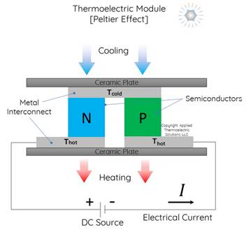
Figure 1‑4. Conceptual scheme of a Peltier cell. Source: Applied Thermoelectric Solutions
There are many other types of heat pump technology in research or used in specific market niches: Stirling engine working as a heat pump, adsorption heat pump, acoustic heat pumps, etc.
1.3 Logic of the compression vapor cycle
In this section, we will provide an intuitive description of the simple mechanical compression cycle, which serves as the basic operating cycle for an electric heat pump. As shown in Figure 1‑1, the heat pump is a device that absorbs thermal energy from a low temperature media (source) and releases it to a higher temperature media (sink). On each of these sides we find a heat exchanger that communicates the internal cycle of the heat pump with the corresponding reservoir. We will begin by analyzing the heat exchanger on the source side, known as the evaporator.
All heat pumps take advantage of the fact that a liquid absorbs heat when it evaporates. This process is easily demonstrated by applying alcohol to your skin: as the liquid evaporates, it cools your skin. Similarly, evaporation-based cooling devices, used since ancient times, create a cooling effect by evaporating water in dry air. Liquids need energy to overcome the intermolecular bonds that hold them in the liquid phase and allow molecules to escape as a gas.
However, unlike these examples, heat pumps do not use water or alcohol as the working fluid. Instead, they rely on specially selected fluids, called refrigerants, which are better suited for the process due to their favorable thermodynamic properties. These refrigerants are chosen for their ability to efficiently absorb and release heat during phase changes (from liquid to vapor and vice versa) under the desired operating temperatures and pressures.
Consider the example in Figure 1‑5: to extract thermal energy from the outdoor air at 10°C, a cooler refrigerant, such as one at 5°C, is required on the other side of the heat exchanger. The heat pump is designed to introduce the refrigerant into the evaporator as a saturated liquid. When this liquid finds a warmer wall, it will evaporate at a constant temperature, absorbing heat from the external environment. This enables the refrigerant to absorb a substantial amount of heat during the phase transition, cooling the air in the process.
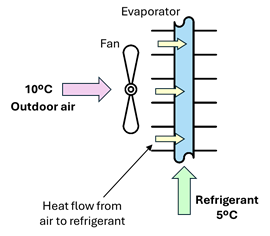
Figure 1‑5. Heat flow direction in the evaporator
The evaporation process is represented in a TS diagram in Figure 1‑6 for the refrigerant R134a. The source temperature is 10°C, and the refrigerant pressure is 350 kPa, resulting in a saturation temperature of 5°C. The refrigerant is introduced in the evaporator as a saturated liquid (with a small fraction of vapor, point 1), which evaporates as it flows along the tube, absorbing heat from the warmer walls. The refrigerant completely evaporates and eventually becomes slightly superheated at the exit of the evaporator (point 2).
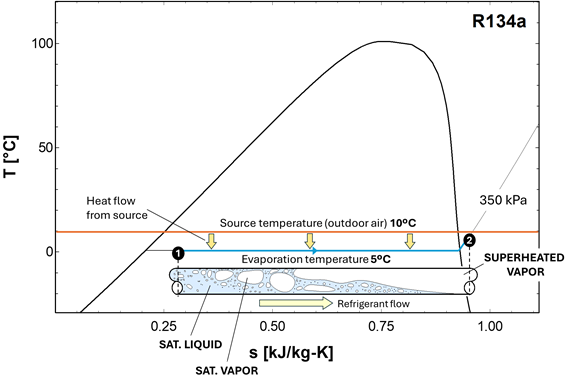
Figure 1‑6. Evaporation of the refrigerant in a TS diagram
Thanks to the characteristics of the evaporation process, we have implemented one step of the heat pump cycle that absorbs heat from the source and stores it as latent energy in the refrigerant. The refrigerant’s saturation temperature can be easily adjusted to a value below the source temperature by acting on the pressure.
The next problem is how to deliver the energy stored in the refrigerant to the sink, which in this example is the indoor environment of a building at 21 °C. This transfer takes place in another heat exchanger, called the condenser. To make heat transfer possible to the indoor environment, the temperature of the refrigerant in the condenser must be well above that of the indoor space, for example 30 °C for a space at 21 °C (see Figure 1‑7). We also need to condensate the refrigerant so that we have liquid again to feed the evaporator in a closed loop. The solution to both requirements is to move to an upper isobar by compressing the vapor.
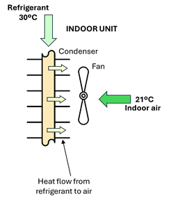
Figure 1‑7. Condensation of the refrigerant
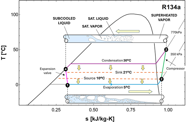
The refrigerant leaving the evaporator as a slightly superheated vapor must first be brought to a much higher temperature and pressure. This is accomplished by the compressor, which raises the pressure of the vapor from the evaporation level to the condensation level (770kPa in this example, see Figure 1‑8). As a result of this compression, the refrigerant temperature increases significantly, reaching a value well above the indoor air temperature (point 3 in Figure 1‑8).
The high-pressure, high-temperature vapor then enters the condenser. As it flows through this heat exchanger, it transfers heat to the indoor environment (sink 21°C in Figure 1‑8). During this process, the refrigerant first cools sensibly until it reaches the saturation temperature (30°C) corresponding to the condenser pressure (770kPa for R134a) and then condenses at nearly constant temperature, releasing a large amount of latent heat. By the end of the condenser area, the refrigerant is fully condensed and may be slightly subcooled to ensure that no vapor remains and improve the operation of the next step.
At this point (point 4), the refrigerant is a high-pressure liquid, which is not suitable for direct introduction into the evaporator. The pressure must be reduced to restore the low saturation temperature required for heat absorption from the source. This pressure reduction is achieved by the expansion valve, where the liquid undergoes a throttling process. The pressure drops abruptly, the saturation temperature decreases, and a small fraction of the liquid flashes into vapor, producing a low-pressure liquid–vapor mixture.
This mixture then re-enters the evaporator, where the cycle repeats. In this way, the heat pump continuously extracts thermal energy from the source, upgrades it to a higher temperature level through compression, and releases it to the sink, operating in a closed thermodynamic loop.
1.4 Simple vapor compression cycle
Figure 1‑8 puts together the four components of the single stage vapor compression cycle. As discussed in the previous section, these components work together to extract heat (Q₀) from a low-temperature reservoir and upgrade and release that energy, together with the compression work, to a high-temperature reservoir (Qc = Q₀ + P). A non-chlorofluorocarbon refrigerant is used as the heat-transfer medium, which circulates within the heat pump. The compressor is normally driven by an electric motor, thus forming an electric heat pump. The technology was developed in the 1850s and has been extensively used since then for heating and cooling of buildings and for commercial refrigeration.
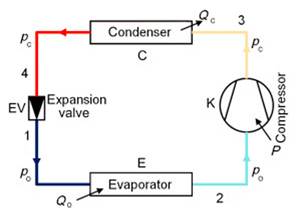
Figure 1‑8. Schematic of a single-stage compression refrigeration system
Now we summarize the cycle steps:
- Evaporation: Low-temperature, low-pressure liquid refrigerant enters a heat exchanger (the evaporator), where it absorbs heat from an external source (air, ground, or water). The refrigerant boils and becomes superheated vapour (it temperature will normally be 5 °C above the saturation temperature)
- Compression: The vapour is then compressed to a higher pressure in the compressor. This mechanical work input raises the refrigerant’s temperature significantly, consistent with the saturation pressure–temperature relationship shown in Figure 1‑9
- Condensation: The high-temperature vapour flows through a second heat exchanger (the condenser), where it transfers heat to the building’s distribution system. As heat is rejected, the refrigerant cools, condenses to a liquid, and is directed toward the expansion device.
- Expansion: The warm liquid refrigerant passes through an expansion valve, where a sharp pressure reduction causes its partial vaporization (frash) and a significant temperature drop. The low-pressure liquid then re-enters the evaporator, and the cycle repeats.
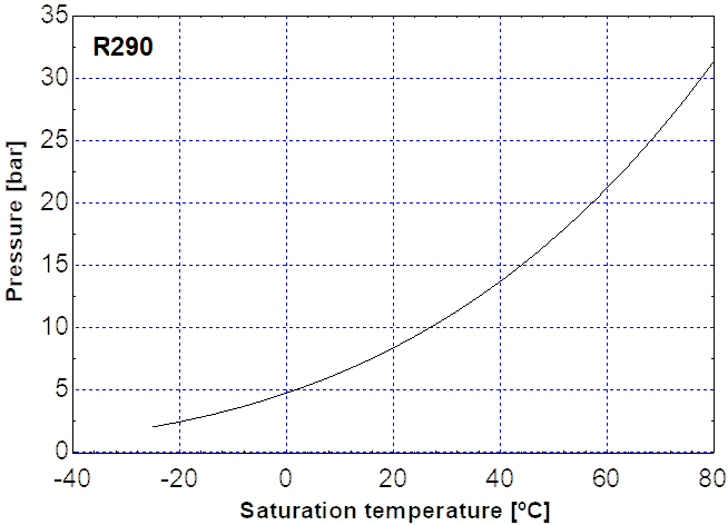
Figure 1‑9. Relationship between saturation temperature and pressure for a common refrigerant
Heat pumps are similar to refrigerators and air-conditioning systems: they use a refrigerant cycle to extract very low-grade heat (usually under 25°C) and upgrade it to a higher temperature. A heat pump consists of three linked systems:
- source, from where heat is extracted, e.g. air or water;
- refrigeration system, which upgrades/generates the heat; and
- heat distribution system, which brings the heat to the points of use, e.g. radiators.
Heat pumps can supply different types of heat distribution systems. Some heat air directly, whereas others provide heat through water.
The closer the evaporator and condenser temperatures, the closer the gas pressure at these points, and the less work the compressor has to do to increase the gas pressure between them. The less work the compressor does, the less electricity it will consume. Therefore, the efficiency of the heat pump is closely linked to the difference in temperature between the heat source and the heat sink (heat distribution system).
1.5 Carnot efficiency and the role of thermodynamic irreversibility
One of the main influences on heat pump efficiency is the difference between the mean temperature in the evaporator and that in the condenser. Where possible, the temperature difference should be reduced by:
- Increasing the temperature of the heat source, or
- Decreasing the temperature of the heat sink (heat distribution system of the building).
Heat pumps are much more sensitive to temperatures in the heat distribution system (and the temperature difference across it), than boilers. This is an important consideration for the design of the heat distribution system.
Heat pumps, air conditioners, and refrigerators utilize heat transfer from cold to hot. They are heat engines run backward. We say backward, rather than reverse, because except for Carnot engines, all heat engines, though they can be run backward, cannot truly be reversed. Heat transfer occurs from a cold reservoir Qc and into a hot one (Figure 1‑10 a). This requires work input W, which is also converted to heat transfer. Thus, the heat transfer to the hot reservoir is Qh = Qc + W. (Note that Qh, Qc, and W are positive, with their directions indicated on schematics rather than by sign.) A heat pump’s mission is for heat transfer Qh to occur into a warm environment, such as a home in the winter. The mission of air conditioners and refrigerators is for heat transfer Qc to occur from a cool environment, such as chilling a room or keeping food at lower temperatures than the environment. A heat pump can be used both to heat and cool a space. It is essentially an air conditioner and a heating unit all in one.
Diagram for a Carnot cycle similar to that in Figure 1‑8 but reversed, following path ADCBA (Figure 1‑10b). The area inside the loop is negative, meaning there is a network input. There is heat transfer Qc into the system from a cold reservoir along path DC, and heat transfer Qh out of the system into a hot reservoir along path BA.
The great advantage of using a heat pump to keep your home warm, rather than just burning fuel, is that a heat pump supplies Qh = Qc + W. Heat transfer is from the outside air, even at a temperature below freezing, to the indoor space. You only pay for W, and you get an additional heat transfer of Qc from the outside at no cost; in many cases, at least twice as much energy is transferred to the heated space as is used to run the heat pump. When you burn fuel to keep warm, you pay for all of it. The disadvantage is that the work input (required by the second law of thermodynamics) is sometimes more expensive than simply burning fuel, especially if the work is done by electrical energy.
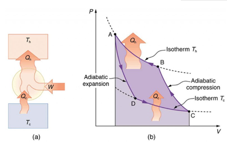
Figure 1‑10. Carnot engine: (a) schematic diagram of heat transfer; (b) diagram for a Carnot cycle reversed [1]
Friction and other irreversible processes reduce heat engine efficiency, but they do not benefit the operation of a heat pump—instead, they reduce the work input by converting part of it to heat transfer back into the cold reservoir before it gets into the heat pump. When a real heat engine is run backward, some of the intended work input W goes into heat transfer before it gets into the heat engine, thereby reducing its coefficient of performance. In Figure 1‑11 W′ represents the portion of W that goes into the heat pump, while the remainder of W is lost in the form of frictional heat (Qf) to the cold reservoir. If all of W had gone into the heat pump, then Qh would have been greater. The best heat pump uses adiabatic and isothermal processes, since, in theory, there would be no dissipative processes to reduce the heat transfer to the hot reservoir.
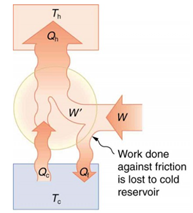
Figure 1‑11. Schematic diagram of heat transfer in a real heat engine [2]
1.6 Application domains: space heating & cooling, domestic hot water
Residential have found to be a successful location to implement the popular application of heat pumps where a large variety of systems exist, depending in part on:
- Whether they are intended for both heating and cooling or only heating, and
- The maximum supply temperature and the heat distribution media (air or water or refrigerant)
Based on their operational functions, heat pumps are classified into four main categories:
- Heating-only heat pumps – Space heating/ water heating applications
- Heating and cooling heat pumps – both space heating and cooling applications
- Integrated heat pump systems – space heating and cooling, water heating, and sometimes exhaust air heat recovery
- Heat pump water heaters – water heating
Heating and hot water
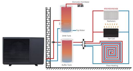
Figure 1‑12. Heat pumps heating and hot water system
Home heating and cooling
Heat pumps are widely used in residential buildings to provide heating in the cold season and cooling in the summer. Due to their ability to transfer heat from the outside environment to the room and vice versa, they can significantly reduce energy costs. Heat pumps can be integrated with water heating systems.
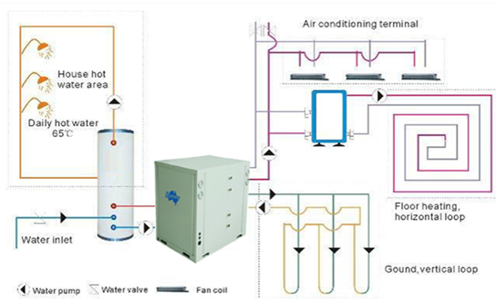
Figure 1‑13. Heat pumps heating, hot water and cooling system [3]
Hot water heat pumps
There are heat pump models designed to prepare domestic hot water. This is an economical and efficient way of providing hot water to the home. Heat pump solutions for DHW heating independently of the heating system. Hot water heat pumps use the air from ancillary rooms such as the basement, storeroom or laundry room. Thanks to the relatively constant temperatures in these areas, hot water heat pumps work highly efficiently, reliably providing water temperatures of up to 65°C. Depending on the model, appliances can also be used for room dehumidification and cooling.
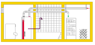
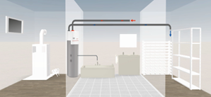
Figure 1‑14. Heat pumps in hot water system [4]
1.7 Classification by heat source (air, water, ground)
Heat pumps may be categorised according to the source of heat and the heat transfer medium used in the heat distribution system:
- An air-to-water heat pump system extracts heat from outdoor air blown across an evaporator. Installation is more straightforward than for a ground- or water-source heat pump, and the annual heat output can be increased significantly without depleting the source. Typically, annual efficiency is lower than for ground- or water-source systems.
- Ground-source heat pumps use an evaporator linked with a water-based heat medium circulating in the source system. Ground-source heat pumps use loops of pipe (in horizontal trenches or vertical boreholes) connected together in a closed-loop system. Ground temperatures fluctuate less throughout the year than air temperatures, which means a higher efficiency for heating during winter, and a higher efficiency for cooling in summer. However, there is a finite thermal resource that can be depleted if not properly managed.
- Heat pumps can also extract heat from water sources (rivers, lakes, the sea, and from groundwater).
According to European legislation, for the heat to be renewable, it must be extracted from the air, the ground (including water from below the ground) or from surface water, such as rivers, lakes and seas.
Air-to-water heat pump
In an air-to-water heat pump system, heat is extracted from outdoor air blown across an evaporator. This type of heat pump can continue to extract heat from air at temperatures as low as approximately – 25°C (depending on the model). However, the water temperature in the heating system and the total heat output may reduce if outside air temperatures are well below 0°C. This in turn will affect the overall efficiency of the system, reducing the coefficient of performance. Some air-to-water heat pumps split the refrigeration cycles between two units: one unit (outside the building) houses the evaporator, and one inside the building houses the condenser. Refrigeration pipework connects the two units. This is a split unit heat pump system. A single evaporator connected to multiple condensers is a multi-split heat pump system. Packaged heat pumps have the entire refrigeration system in a single enclosure.
Several small air-source heat pumps can be connected together for a large capacity system. To configure this system, some models have built-in control functionality. Usually, the upper limit is ten units connected together. Single, small packaged units can supply up to approximately 60 kW of heating. Cascaded units can supply up to around 500 kW.
The advantages of air-to-water systems include:
- Straightforward installation compared to ground- or water-source heat pumps;
- Unlike ground-source heat pumps, the number of operating hours (and, therefore the heat delivered) can be increased significantly without depleting the source;
- The design process is considerably more straightforward; and
- Operating problems are often less frequent and easier to solve.
Air-source heat pumps can also be used in combination with other types of heat pump to provide top-up or to add capacity to the system retrospectively (e.g. where a ground-source system has been installed, but there is limited ground space available).
The main disadvantage of air-to-water systems is that the annual efficiency is usually lower than that of ground- or water-source systems. Air temperatures usually vary more than ground or water temperatures. In winter, lower air temperatures coincide with higher heat demand. Air-source heat pumps can be more efficient (than ground- or water- source pumps) during the summer months, but this is also a time when heat demand is low.
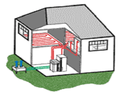
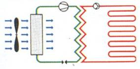
Figure 1‑15. Air-to-water heat pump system[5]
The efficiency of reversible air-to-water heat pumps is often significantly lower when providing cooling than the efficiency of ground- or water-source versions. Air-source heat pumps cannot use direct cooling from the source in the way that ground- or water-source heat pumps can.
Freezing and defrost cycle: For the evaporator to work, its surface temperature must be lower than the temperature of the outdoor air blown across it. If the surface temperature is below the dew point of the air, some water vapor in the air will condense on the evaporator surface. This condensate must be directed to a drain or a soakaway. If it collects around the base of the heat pump, it can freeze due to the cold air leaving the evaporator and create a hazard. At sub-zero temperatures, the condensate will also freeze on the evaporator surface, blocking the airflow and forcing the system to run a defrost cycle.
Air-to-air heat pumps
In contrast to air-to-water heat pump systems, which are used to warm or cool water, air-to-air systems heat or cool the air directly in the room or building. Therefore, air-to-air heat pump systems often have air handling units and blowers as part of their indoor equipment. Similar in appearance to commonplace home air conditioners.

Figure 1‑16. Schematic illustration of an air-to-air heat pump system: heating mode, and cooling mode[6].
Ground-to-water and water-to-water heat pump
Many models of heat pumps that are designed for a water-based medium in the evaporator can be used in both water- and ground-source systems.
Ground-source heat pumps use loops of pipe (either in horizontal trenches or vertical boreholes) connected together to form a closed loop system. The heat medium used is a mixture of water, antifreeze (such as ethylene glycol or propylene glycol), a corrosion inhibitor and a biological growth inhibitor. Many ground-source heat pumps can be used with either open or closed source systems. Heat pumps that use refrigerant pipework in the ground are known as direct exchange geothermal heat.
There are two types of ground-source heat pump systems: those which extract heat from the ground using pipework laid in horizontal trenches around 1 m to 2 m deep; and those which extract heat using loops of pipes installed in vertical boreholes.
Vertical boreholes
Vertical, closed loop collectors are installed in boreholes, each of around 100 m to 200 m deep. In each borehole, one or two loops of pipe are inserted vertically, and the borehole is backfilled with materials such as thermal grout. The number and depth of boreholes required depends on the heat pump capacity, the total amount of heat to be extracted per year and the type of rock/soil. Heat outputs typically vary from around 10 W/m to around 55 W/m of borehole. Several factors affect the cost of boreholes. For example, on a site with solid consolidated rock overlain by superficial deposits, the greater the depth of superficial deposits (e.g. soil) that sit on top of the bedrock, the more casing is needed and the greater the cost per borehole. Also, since some soil types can have poor thermal properties, more boreholes may be required.
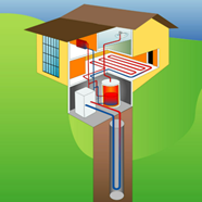
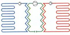
Figure 1‑17. Ground-to-water heat pump systems. Vertical boreholes (closed-loop systems)
The thermal properties of the bedrock vary significantly depending on the rock type, but also depending on other factors: whether it is consolidated or highly fractured, and whether it is dry or there is a water flow through it. A borehole could penetrate through multiple rock types and superficial deposits. The heat output of each borehole depends on the thermal properties and the depth of the borehole. These have to be determined for each borehole in order to estimate heat output. A thermal response test may be performed on site in order to measure ground thermal properties, which may aid in system design and sizing.
The heat recovery from closed loop boreholes in consolidated rock is from true geothermal energy (as well as from any groundwater flows). Therefore, the temperatures achieved tend to increase slightly with depth. However, there are practical limits to the depths of boreholes that can be drilled, depending on the rock type and the type of drilling used. You should conduct a desk-based assessment of the ground conditions to inform the feasibility and outline design, and then drill a test borehole to inform the detailed design.
Horizontal loops
Horizontal ground loops can be installed in trenches of between 1 m and 2 m deep. Horizontal ground outputs are typically in the range of 5 W/m to 20 W/m of pipe but can be from 1 W/m to 40 W/m. The loops of pipe can be laid out in straight lengths or in coils, known as ‘slinkies’. Horizontal loops usually cost less to install than vertical boreholes, but they require a lot of ground area when providing space heating, usually several times the total floor area of a building being heated. For that reason, horizontal ground loops are typically not used for large systems. The soil type makes a big difference to the amount of heat that can be extracted per square metre. Soils that retain moisture tend to have higher heat outputs than well-draining soils (e.g. installations in dry sand will require several times more ground area than those in wet clay).
The specific heat extraction rate from ground loops can typically be between 10 W/m2 and 40 W/m2 of ground area.1 Horizontal trenches depend significantly on rainfall to replenish the heat extracted and cannot usually be installed under hardstanding.
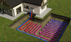
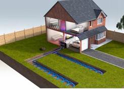
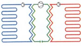
Figure 1‑18. Ground-to-water heat pump systems. Horizontal loops (closed-loop systems) [7]
Water-to-water heat pump
A closed loop water-source system usually involves laying loops of pipework or metal heat exchangers in the water. The flow of water around the system is solely due to the natural flow of the water and convection currents from cooled water sinking around the heat exchangers. The heat exchangers must always be in contact with the water and not float to the surface. Often, they are fixed to weights such as concrete blocks. Inspection is required as part of a maintenance regime, and can be expensive, particularly in deep water. A closed loop system for use in the sea must be designed to withstand wave and tidal motion.
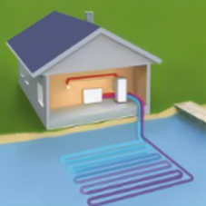
Figure 1‑19. Closed-loop systems (water-source)
In an open loop system, water is pumped from a sea, river or lake, or from groundwater, passed through a heat exchanger and then returned to the source. The water must be filtered to ensure that the heat exchanger does not become blocked by debris. The water quality must also be analysed. Acidic water (e.g. peaty water) limits the choice of materials that can be used, and this can increase costs. Dissolved minerals also build up on system components, necessitating frequent cleaning.
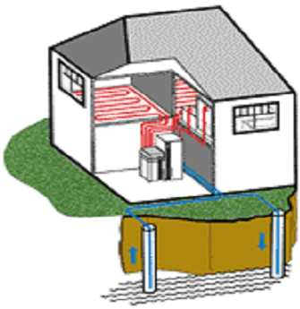
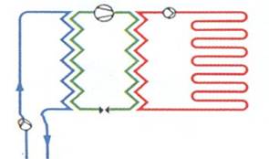
Figure 1‑20. Water-to-water heat pump systems. Water-source (open-loop systems) [8]
When there is an aquifer beneath a site, boreholes can be drilled into the aquifer and water pumped out of it to extract heat. This is an open loop system. The water is usually then returned to the ground through a second borehole. Reinjecting the water into the same aquifer conserves the water resources.
The capacity of a groundwater system depends on the water level recovery rate, the temperature of the groundwater and the nature of the groundwater flow. The amount of energy needed to pump the water can be significant and depends on factors such as the depth of the borehole and the permeability of the aquifer.
1.8 Emerging and advanced types
It is possible to connect multiple heat pumps to the same ground- or water-source system. This means that several buildings (or heat loads within a building) can share the source system and have individual heat pump and heat distribution systems suited to each building. Integrating heating and cooling loads into one source system can maximise energy efficiency through heat recovery, maximise the efficiency of the heat pump systems, and minimise the size and cost of the source array. Such systems have complex heat flow arrangements that will require software simulation of the loads to be met and the source system.
Simultaneous Heating and Cooling with CO2. High Temperature Heat Pumps
The fundamental principle of heat pumps is to absorb heat at low-temperature levels and dispense it as useful heat at a higher temperature. A heat pump uses heat sources that are normally technically not usable. For instance, a heat pump can increase the temperature of geothermal energy from 10 °C to 40 °C. In addition to geothermal energy, it can utilise surface water and seasonal heat stores as heat sources. But a heat pump only lives up to its full potential in terms of performance and sustainability when it converts waste heat from industrial production, exhaust air from air-conditioning systems, or waste heat from chillers and then makes it available as heat output at a higher temperature level. Using a heat pump generates significant energy savings because it optimises such processes.
With the help of CO2, a natural refrigerant – whose technical name is R-744 – it is possible to achieve effective temperatures of up to 110°C. This opens up applications in the fields of district heating, heat provision in industrial process and drying technology. Standard heat pumps are usually inadequate for heating potable water. When water is heated, temperatures of 60 to 70 °C need to be achieved in order to remove the risk of legionella. These high temperatures are usually generated by means of inefficient electrical element heating.
High temperature heat pumps like Engie’s thermeco can provide both Low-Temperature Hot Water (LTHW) and Domestic Hot Water (DHW) without the need for supplementary electrical heating. CO2 is harmless to use (classified as A1), cheap to procure, and, with a GWP of 1, has no harmful effects on the earth’s atmosphere. CO2 (in subcritical mode) has become standard for use in refrigeration – for instance, in the cooling and storage of food.
At higher temperatures (supercritical mode), it is possible to implement heat pump applications that are highly efficient in their respective temperature ranges. Supercritical applications are a relatively new field of application for CO2 as a refrigerant. CO2 is predestined for all applications that require cooling and heating at the same time, such as an air-conditioned hotel with a swimming pool and sauna, for example. In the long term, a trend towards natural refrigerants seems likely, due to the F-gas Regulation, which is currently leading to restrictions on volumes of halogenated refrigerants.
A scheme of the layout of the new hybrid heat pump in heating and cooling mode is show in Figure 1‑21.
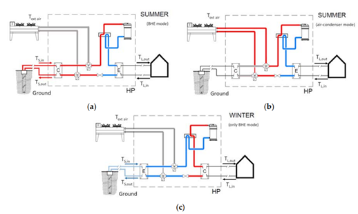
Figure 1‑21. Schemes of the new hybrid heat pump: (a) operation in cooling mode using borehole heat exchangers; (b) operation in cooling mode using air‐condenser; (c) operation in heating mode using borehole heat exchangers [9]
In cooling mode, the heat pump can use the water-condenser coupled to the borehole heat exchangers (Figure 1‑21 a) or, alternatively, the air-condenser (Figure 1‑21 b); the switch between the borehole heat exchangers and the air-condenser is controlled via an appropriate control strategy based on the external air temperature. In heating mode, only the ground through the borehole heat exchangers is used by the heat pump as a heat source (Figure 1‑21 c).
1.9 Review Questions
- Identify the four general components of an HVAC system and briefly describe the role of each (thermal production, storage, distribution, terminal units).
- Describe the four main stages of the vapor compression refrigeration cycle used in most heat pumps.
- How does the temperature difference between the evaporator and condenser affect the efficiency of a heat pump?
- What are the main differences between conventional vapor compression heat pumps and transcritical CO₂ heat pumps in terms of operating temperature and application?
- Explain the concept of Carnot efficiency and how thermodynamic irreversibility impacts the coefficient of performance (COP) of a heat pump.
- What are the three linked systems that constitute a heat pump, and what role does each play in the heating process?
- Compare air-to-water and ground-source heat pumps in terms of installation complexity, efficiency, and typical applications.
- What are the advantages and disadvantages of air-source heat pumps, especially in cold climates?
- How do hybrid heat pump systems operate, and what benefits do they offer compared to single-source systems?
- Why is it important to minimize the temperature difference between the heat source and heat distribution system in heat pump design?