Lesson 1. Fundamentals of Heat Pumps
February 9, 2026Lesson 4.Refrigeration Circuit Components I: Compressors
February 9, 2026Welcome to this lesson! Start by watching a recap video of this lesson.
Click on the gear icon to choose subtitles of your preferred language.
2.1 Step-by-step Intuitive introduction to basic vapour compression process
The Vapor Compression Refrigeration Cycle involves four components: compressor, condenser, expansion valve/throttle valve and evaporator. It is a compression process, whose aim is to raise the refrigerant pressure, as it flows from an evaporator. The high-pressure refrigerant flows through a condenser/heat exchanger before attaining the initial low pressure and going back to the evaporator. A more detailed explanation of the steps is as explained below.
Step 1: Compression
The refrigerant (for example R-717) enters the compressor at low temperature and low pressure. It is in a gaseous state. Here, compression takes place to raise the temperature and refrigerant pressure. The refrigerant leaves the compressor and enters to the condenser. Since this process requires work, an electric motor may be used. Compressors themselves can be scroll, screw, centrifugal or reciprocating types.
Step 2: Condensation
The condenser is essentially a heat exchanger. Heat is transferred from the refrigerant to a flow of air or water. As the refrigerant flows through the condenser, it is in a constant pressure. One cannot afford to ignore condenser safety and performance. Specifically, pressure control is paramount for safety and efficiency reasons. There are several pressure-controlling devices to take care of this requirement.
Step 3: Throttling and Expansion
When the refrigerant enters the throttling valve, it expands and releases pressure. Consequently, the temperature drops at this stage. Because of these changes, the refrigerant leaves the throttle valve as a liquid vapor mixture, typically in proportions of around 75 % and 25 % respectively. Throttling valves play two crucial roles in the vapor compression cycle. First, they maintain a pressure differential between low- and high-pressure sides. Second, they control the amount of liquid refrigerant entering the evaporator.
Step 4: Evaporation
At this stage of the Vapor Compression Refrigeration Cycle, the refrigerant is at a lower temperature than its surroundings. Therefore, it evaporates and absorbs latent heat of vaporization. Heat extraction from the refrigerant happens at low pressure and temperature. Compressor suction effect helps maintain the low pressure. There are different evaporator versions in the market, but the major classifications are liquid cooling and air cooling, depending whether they cool liquid or air respectively.
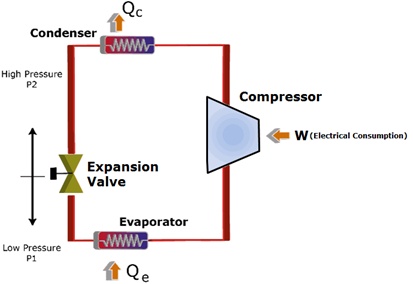
Figure 2‑1. Schematic representation of vapour compression process steps [1]
A HP is a thermal installation that is based on a reverse Carnot thermodynamic cycle, which consumes drive energy and produces a thermal effect. Any HP moves (pumps) heat ES from a source with low temperature ts to a source with a high temperature tu, consuming drive energy ED.
A heat source can be:
- a gas or air (outdoor air, warm air from ventilation, hot gases from industrial processes),
- a liquid called ‘generic water’: surface water (river, lake or sea), groundwater, or discharged hot water (domestic, technologic or recirculated in cooling towers); or
- ground, with the advantage of accessibility.
Heat consumer. The HP yields thermal energy at a higher temperature, depending on the application of the heat consumer. This energy can be used for:
- space heating, which is related to low-temperature heating systems: radiant panels (floor, wall, ceiling or floor-ceiling), warm air or convective systems; or
- water heating (pools, domestic or technologic hot water). The heat consumer is recommended to be associated with a cold consumer. This can be performed with either a reversible (heating cooling) or a double-effect system. In cooling mode, an HP operates exactly like central A/C.
Drive energy. HPs can be used to drive different energy forms:
- electrical energy (electric compressor)
- mechanical energy (mechanical compression with expansion turbines)
- thermomechanical energy (steam ejector system)
- thermal energy (absorption cycle); or
- thermoelectrical energy (the Peltier effect).
2.2 Main components overview with annotated system diagrams
Theoretical Cycle
The basic vapour-compression cycle is considered as one with isentropic compression, with no superheat of vapour and no subcooling of liquid (Figure 2‑2).
Operational processes are outlined next:
1−2: isentropic compression in the compressor, which leads to increased pressure and temperature from the values corresponding for evaporation p0, t0 to those of the condensation pc, t2>tc
2−2′: isobar cooling in the condenser at pressure pc from the temperature t2 to t2′=tc
2′−3: isotherm–isobar condensation in the condenser at pressure pc and temperature tc
3−4: isenthalpic lamination in expansion valve, leading the refrigerant from 3 state of the liquid at pc, tc in 4 state of wet vapour at p0, t0
4−1: isotherm–isobar evaporation in the evaporator at pressure p0 and temperature t0.
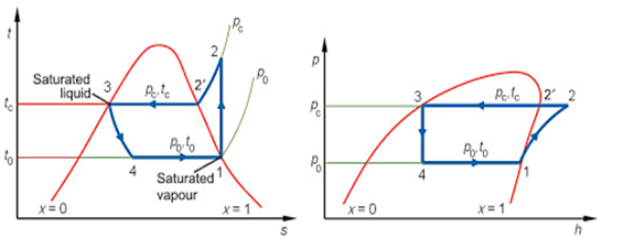
Figure 2‑2. Single-stage vapour-compression process in t–s and p–h diagrams [2]
In a theoretical vapour-compression cycle, the refrigerant enters the compressor at state 1, as saturated vapour, and is compressed isentropically to the condensation pressure. The refrigerant temperature increases during this isentropic compression process to well above the temperature of the surrounding medium. The refrigerant then enters the condenser as superheated vapour at state 2 and leaves as saturated liquid at state 3 as a result of heat rejection to the surroundings. The refrigerant temperature at this state is still greater than the temperature of the surroundings. The saturated liquid refrigerant at state 3 is throttled to the evaporation pressure by passing it through an expansion valve. The refrigerant temperature drops below the temperature of the cold environment during this process. The refrigerant enters the evaporator at state 4 as a low-quality saturated mixture, and completely evaporates by absorbing heat from the cold environment. The refrigerant then leaves the evaporator as saturated vapour and re-enters the compressor, completing the cycle [3].
2.3 Photo illustrations and labelled schematics of real commercial units
Heat pump compressor
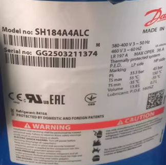
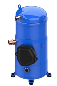
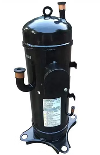
Figure 2‑3. Heat pumps Scroll compressor: (a) Danfoss heat pump Scroll compressor, SH184A4ALC [4] ; (b) Mitsubishi DC Inverter Compressor Gtc5150nh48L R410A [5]
Heat pump condenser
Figure 2‑4 shows the characteristic plate of a typical condenser, reporting the following important data:
1 – Serial Number,
2 – Model Number.
3 – Factory Charged. This will tell you whether the system uses the older R-22 refrigerant, which is being phased out, or the current R-410A.
4 – RLA. The Running Load Amperage is the amount of current in amps that the compressor motor will draw after startup, when operating.
5 – LRA. The Locked Rotor Amperage is the necessary surge of electricity required to overcome inertia and start up the compressor. This number will be important to you if you plan to run your a/c system using a generator during a power outage. The generator must be able to handle this brief surge of amps, usually 4 or 5 times the RLA.
6 – Max Circuit Breaker or Fuse. This is always approximately twice the RLA of the compressor. The only time this number becomes a problem is when the system has been changed out for a newer, more energy one, and the breaker for the circuit is not also changed out to a lower amperage rating.
7 – Date of Manufacture. Sometimes the date of manufacture is directly stated and it is not necessary to decode the serial number. Trane, for example, often places the date of manufacture at the upper right of the data plate.
8 – Heat Pump or Cooling Air Conditioner. Somewhere near the bottom of the data plate, and often in small letters, it will state whether the condenser is a heat pump (contains a device to reverse the flow of refrigerant from cooling to heating) or a cooling air conditioner (only functions in cooling mode, and usually part of a system with gas furnace).
9 – Name of Manufacturer. This is often also small letters and may be an acronym. For example, CAC/BDP is a division of the Carrier Corporation.
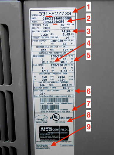
Figure 2‑4. Heat pump condenser labeled [6]
Evaporator for heat pumps

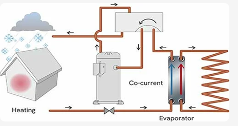
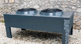
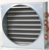
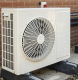
Figure 2‑5. Heat pumps evaporator: a )For ground-to-water and water-to-water heat pump; b) for air-to-water heat pump
Expansion valve
On its return to the evaporator from the condenser the high-temperature, high-pressure liquid refrigerant must be changed to the low-temperature, low-pressure liquid that enters the evaporator. This is usually achieved by a throttling device known as the expansion valve.
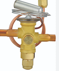
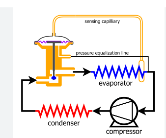
Figure 2‑6. A thermostatic expansion valve [9]
When the hot liquid passes through this valve, not only will its pressure be reduced but at the same time its temperature will drop. As the pressure drops, refrigerant starts to evaporate in the valve and the heat of evaporation is taken from the refrigerant itself which causes its temperature to drop and the result is a low-temperature, low-pressure mix of liquid and vapour, which then enters the evaporator.
2.4 Basic representation in p-h and t-s diagrams
Real Cycle
- The real operational processes (Figure 2‑7) of a HP deviate from the component processes of the theoretical cycle in the following ways:
- the compression process 1-2 in the compressor is adiabatic, but irreversible,
- the heat exchange from the evaporator and the condenser is realised with finite temperature differences, imprinting on these processes an irreversible mark; the average temperature of the cold source ts is higher than the evaporation temperature t0, with the difference Δt0, and the average temperature of the heat source tu is lower that the condensation temperature tc, with the difference Δtc.
- the refrigerant flow through the system experiences pressure losses; and
- the equipment and pipes which the working fluid runs through exchange heat with the environment.
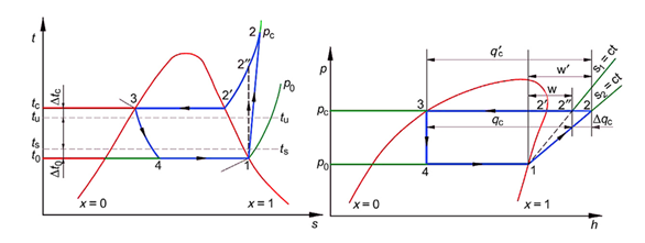
Figure 2‑7. Real operation process in t-s and p-h diagrams [10]
The irreversibility of the compression process increases the specific compression work to w/ and increases the specific thermal load at condensation by Δqc. To assess the deviation in the degree of compression process 1-2 versus 1-2//, the (adiabatic) efficiency ηi of the compressor is defined as:
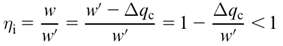
where w is the specific isentropic compression work; w/ is the specific adiabatic irreversible compression work; and Δqc is the thermal load increase due to the irreversible compression process 1-2, given the isentropic process. It follows that the real thermal efficiency COPr (εr) of the cycle is given by:
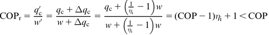
where q/c is the specific heat load at condensation in the real cycle with irreversible adiabatic compression. The effective value of the thermal efficiency COPe for the HP is diminished because of the mechanical and electrical losses of the electric motor-compressor assembly:
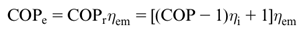
where ηem is the electromechanical efficiency of compressor-motor assembly.
2.5 Concepts of subcooling and superheating and their impact on performance
In the simplest saturated refrigeration cycle, both the refrigerant vapor and liquid are assumed to be saturated before entering the compressor’s suction and expansion valves, respectively. Saturated vapor can be further superheated by adding a superheating procedure before entering the compressor which will help to absorb more heat. Similarly, the subcooling procedure will cause a saturated liquid to get subcooled in front of the expansion valve allowing it to lose more heat. As will be seen in the following section, subcooling, and superheating are two of the methods for increasing the refrigeration cycle’s efficiency[11]. They are typically used to improve performance (COP) and to avoid specific issues within the machines.
Liquid-suction heat exchanger (LSHX)
The P-h diagram and schematic of a LSHX air conditioning cycle are displayed In Figure 2‑8. Assuming a saturated vapor phase at point 1 and a saturated liquid phase at point 3 in the basic cycle, using LSHX, we can transfer heat from the condenser’s exit (the liquid line) to the compressor’s inlet (the suction), when this happens, the saturated liquid transitions to the sub-cooled liquid state (point 3’), while the saturated vapor converts to the superheated vapor state (point 1’). The degrees of subcooling and superheating are respectively the temperature difference between points 3 and 3’, and between points 1 and 1’. Consequently, the amount (h1’-h4’) is bigger than (h1-h4) which represents an increase in the cooling capacity[12].
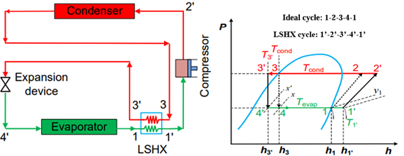
Figure 2‑8. Vapor compression refrigeration cycle with LSHX: schematic sketch and the P-h diagram [13]
On top of that, it stops the liquid refrigerant from going into the compressor and the vapor from passing into the expansion mechanism. The increased superheating in the compressor suction is a drawback of employing LSHX since it raises the discharge temperature. Therefore, the superheating will increase the workload on the compressor. In other words, if cooling capacity rises thanks to LSHX, superheating rises right alongside it. Therefore, an increase in cooling capacity and compressor effort is directly proportional to the improvement in an air conditioner’s performance. The COP will grow positively if the additional cooling capacity exceeds the additional work required by the compressor, and negatively otherwise.
Ambient subcooling
Vapor compression refrigeration systems with ambient subcooling use an additional heat exchange surface, which interacts with the ambient to subcool the liquid refrigerant. This method is used to downstream the condenser, increase the heat rejection to the ambient, and get higher COP. Another method described in[14], is combining a separate heat exchanger (called the sub-cooler) and the condenser into one massive unit, under normal conditions, the sub-cooler in this setup is intended to reduce the temperature by 8°𝐶. More heat transfer area is used since a lower condensing pressure allows for this. Therefore, the restriction on the expansion device must be increased to accomplish the targeted refrigerant subcooling.
Superheating
There is a considerable chance that small particles of unvaporized liquid will be present in the vapor when the suction vapor is taken directly from the evaporator into the suction intake of the compressor without at least a minor amount of superheating. When wet vapor is sucked into the compressor’s cylinder through wet suction, the compressor will not function properly and it might even break down, not to mention have its output energy lowered. When compared to the saturated cycle, the superheated cycle has a larger refrigerating impact per unit mass of refrigerant. The COP for the superheated cycle is bigger than that of the saturated cycle because the rise in the refrigerating effect is proportionally more than the increase in the heat of compression. Superheating can be found at the end of the evaporator, in the suction pipelines, or in the liquid to-suction heat exchanger, either inside or outside the refrigerated area.
In most cases, superheating and subcooling procedures are applied for improving the system efficiency. If the simple refrigeration system is compared to subcooled and superheated refrigeration system, as shown in Figure 2‑8Figure 2‑9, then the refrigerating effect per unit mass is greater by an amount equal to the amount of superheat. Since the refrigerating effect per unit mass is greater for the superheated cycle than for the saturated cycle, the mass flow rate of refrigerant per unit capacity is less for the superheated cycle than for the saturated cycle. Even though the specific volume of the suction vapour and the heat of compression per unit mass are both greater for the superheated cycle than for the saturated cycle, the volume of vapour compressed per unit capacity and the power required per unit capacity are both lower for the superheated cycle than for the saturated cycle. This is because of the reduction in the mass flow rate. For the superheated cycle, both the refrigerating effect per unit mass of refrigerant and the heat of compression per unit mass of refrigerant are greater than for the saturated cycle. However, since the increase in the refrigerating effect is proportionally greater than the increase in the heat of compression, the COP for the superheated cycle is higher than that of the saturated cycle.
The superheating of the suction vapour in an actual cycle usually occurs in such a way that part of the heat taken by the vapour in becoming superheated is absorbed from the refrigerated space and produces useful cooling. The portion of the superheat that produces useful cooling will depend on the individual application, and the effect of the superheating on the cycle will vary approximately in proportion to the useful cooling accomplished. Regardless of the effect on capacity, except in some few special cases, a certain amount of superheating is usually unavoidable and, in most cases desirable. When the suction vapour is drawn directly from the evaporator into the suction inlet of the compressor without at least a small amount of superheating, there is a good possibility that small particles of unvapourized liquid will be entrained in the vapour. Such a vapour is called a wet vapour. Wet suction vapour drawn into the cylinder of the compressor adversely affects the capacity of the compressor. Furthermore, since refrigeration compressors are designed as vapour pumps, if any appreciable amount of unvapourized liquid is allowed to enter the compressor from the suction line, serious mechanical damage to the compressor may result. Since superheating the suction vapour eliminates the possibility of wet suction vapour reaching the compressor inlet, a certain amount of superheating is usually desirable. Again, the extent to which the suction vapour should be allowed to become superheated in any particular instance depends on where and how the superheating occurs and, on the refrigerant, used.
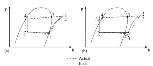
Figure 2‑9. P–h diagrams of: (a) typical refrigeration cycle; and (b) subcooled and superheated refrigeration cycle [15]
Superheating of the suction vapour may take place in any one or in any combination of the following places:
1. At the end of the evaporator.
2. At the suction piping installed inside the refrigerated space (referred to as a drier loop).
3. At the suction piping located outside the refrigerated space.
4. At the liquid-suction heat exchanger.
Effects of subcooling
On the P–h diagram in Figure 2‑9, a simple saturated cycle is compared with one in which the liquid is subcooled. When the liquid is subcooled before it reaches the expansion valve, the refrigerating effect per unit mass is increased. Because of the greater refrigerating effect per unit mass, the mass flow rate of refrigerant per unit capacity is less for the subcooled cycle than for the saturated cycle. It should be noted that the refrigerant vapour entering the suction inlet of the compressor is the same for both cycles. For this reason, the specific volume of the vapour entering the compressor will be the same for both the saturated and subcooled cycles and, since the mass flow rate per unit capacity is less for the subcooled cycle than for the saturated cycle, it follows that the volume of vapour that the compressor must handle per unit capacity will also be less for the subcooled cycle than for the saturated cycle. Because the volume of vapour compressed per unit capacity is less for the subcooled cycle, the compressor displacement required for the subcooled cycle is smaller in comparison with saturated cycle.
It should also be noted that the heat of compression per unit mass is the same for both the saturated and subcooled cycles. This means that the increase in refrigerating effect per unit mass resulting from the subcooling is accomplished without increasing the energy input to the compressor. Any change in the refrigerating cycle that increases the quantity of heat absorbed in the refrigerated space without causing an increase in the energy input to the compressor will increase the COP of the cycle and reduce the power required per unit capacity. Subcooling of the liquid refrigerant can and does occur in several places and in several ways. Very often the liquid refrigerant becomes subcooled while stored in the liquid receiver tank or while passing through the liquid line by giving off heat to the surrounding air. The gain in system capacity and efficiency resulting from the liquid subcooling is very often more than sufficient to offset the additional cost of the subcooler, particularly for low temperature applications.
2.6 Use of intermediate heat exchangers to improve cycle efficiency
In order to increase the energy efficiency, the cycle COP need to be enhanced. Many innovations can be used, one is to utilize internal heat exchanger (IHX).
The refrigeration cycle COP can be improved by increasing super-heating and sub-cooling or recovering expansion losses. Sub-cooling and super-heating can be increased by using different methods, including suction line heat exchangers, mechanical sub-cooling, and thermo-electric sub-cooling. The selection of the most suitable sub-cooling/super-heating method depends on the application and is highly related to the refrigerant properties.
Klein et al.[16] studied the effect of applying a SLHX (Suction-Liquid Heat Exchanger) on the COP of the refrigeration cycle using a group of refrigerants. The study showed a strong relationship between the system COP improvement and the refrigerant thermodynamic properties. In addition, it showed that the SLHX is more effective for refrigerants with a lower latent vaporization temperature and heat capacity, mainly when the system operates on a relatively high temperature lift. Furthermore, the authors of this study concluded that the SLHX was more efficient for systems that used R-410a, R134a, R-290 and R-404; simultaneously, it showed the best results with R-744 (carbon dioxide). However, it was detrimental with R-32 and R-717 (Ammonia). Hwang et al.[17] proposed a SLHX for high-temperature heat pump applications and reported a COP improvement of 7% for the single-stage compression cycle and 18% for the double-stage compression cycle. The reason for the difference in performance was not clearly discussed, but could be referred to the higher temperature difference in the case of double-stage compression, which allows for a more efficient heat transfer process within the SLHX.
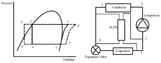
Figure 2‑10. The components and pressure/enthalpy diagram of the VCC (vapor compression cycle) with a SLHX [18]
2.7 Review Questions
- Explain the difference between a monoblock heat pump and a split-system heat pump. What are the installation implications of each?
- Differentiate between the ideal and real vapour compression cycles. Identify the main sources of irreversibility and discuss their impact on system performance.
- Explain the effect of compressor efficiency on the COP of the heat pump. Include the concept of isentropic efficiency in your answer.
- Using the P–h diagram, outline the four main processes of the vapour compression cycle. How does the diagram help engineers analyse system performance?
- The compression process is adiabatic but irreversible in real systems. Explain why this occurs and how it influences the heat transfer rate in the condenser.
- Discuss the thermodynamic function of subcooling and superheating. Under what conditions can these processes enhance or reduce the overall efficiency of a heat pump?
- Evaluate the benefits of using a LSHX in the vapour compression cycle. For which refrigerants or applications is this approach most effective?
- Compare the theoretical Carnot cycle with the vapour compression cycle used in practical heat pumps. What assumptions make the Carnot cycle unachievable in real systems?