Lesson 2. The Vapour Compression Cycle
February 9, 2026Lesson 8.Ancillary Components in Heat Pump Systems
February 9, 2026Welcome to this lesson! Start by watching a recap video of this lesson.
Click on the gear icon to choose subtitles of your preferred language.
4.1 Basic function and thermodynamic role of the compressor
Compression is the first step in the refrigeration cycle, and a compressor is the piece of equipment that increases the pressure of the working gas. Refrigerant enters the compressor as low-pressure. This compresses the low temperature, low pressure gas into a high-pressure gas, which causes it to increase in temperature to a high temperature gas. It creates the low (suction) and high (delivery) pressures which enables phase change (liquid-gas-liquid) to occur at different, more favourable temperatures.
Compressors are designed to increase the pressure of a gas by means of a work input. In the case of refrigerators or heat pumps, the compressor operates on the refrigerant in order to increase the pressure from that of the evaporator to that of the condenser. There are various types of compressors. The choice depends particularly on the pressure ratio required as well as the flow rates of the gas. Rotary type compressors are used for high mass flow rates and low-pressure ratios. Reciprocating type compressors are used for low mass flow rate and high-pressure ratios. In the rotary type compressors, the flow is steady whereas in the reciprocating type compressors, the flow is pulsating. Figure 4‑1 shows a reciprocating type compressor. As the piston moves towards the left, the fluid inside the cylinder is compressed and exits through the delivery port. When the piston moves to the right, fluid enters the cylinder from the intake port. This motion is repeated at a particular frequency or speed of the reciprocating piston.
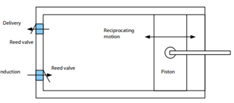
Figure 4‑1. A reciprocating type compressor cylinder [1]
In the rotary type compressor shown in Figure 4‑2, an eccentric rotor having a number of vanes rotates in 1 seal off different segments. The gas is introduced in a segment and is compressed during the rotor. Vane type compressors are quite common in domestic refrigerators, freezers and air-conditioners. Other rotary compressors include screw type compressors, scroll compressors and turbo compressors.
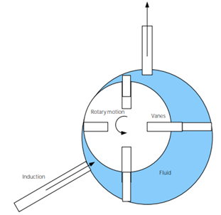
Figure 4‑2. A rotary vane type compressor [2]
A compression process is in practice irreversible. Hence the process is not really performed at a constant entropy. The entropy of the end state after compression is higher than the initial state, in line with the second law of thermodynamics. The vapour compression T-s diagram is shown here with the compressor irreversibilities included (Figure 4‑3). The dotted line shows the actual process undergone in the compressor. The bold line from 1 to 2s shows the compression process if the compression process was isentropic.
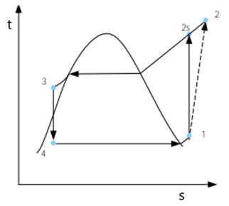
Figure 4‑3. T-s diagram for the vapour compression refrigeration cycle including the isentropic efficiency of the compressor
4.2 Overview of compressor types
The compressor is the heart of the heat pump. All the technical characteristics and parameters of the installation depend on the compressor. Below are the main types of compressors used in steam-compressor heat pump units:
- rotary, mainly used for low power installations. In modern air heat pumps, two-rotor compressors are most often used, which are characterized by increased resource and reliability. Thanks to this design, the compressor can work at a low rotation speed, thereby reducing the number of start and stop cycles, which significantly increases the efficiency of heat pumps. The use of two rotors also reduces vibration and noise.
- scroll, the most common for the configuration of heat pumps of small and medium power. The advantages of such compressors are: high efficiency, noiselessness during operation, durability, high reliability (insignificant number of moving parts).
- piston or reciprocating, for installations of medium and high power
- screw, for high power systems.
The main types of HP compressors according to European Heat Pump Association are illustrated in Figure 4‑4 .
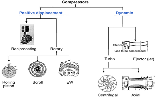
Figure 4‑4. Types of heat pump compressors [3]
Compressors used in refrigeration systems are often described as being hermetic, open or semi-hermetic. Typically, in hermetic and most semi-hermetic compressors, the compressor and motor driving the compressor are integrated and operate within the refrigerant system. The motor is hermetic and is designed to operate, and be cooled by, the refrigerant being compressed. The disadvantage of hermetic compressors is that the motor drive cannot be repaired or maintained, and the entire compressor must be removed if a motor fails. An open compressor has a motor drive which is outside of the refrigeration system, and provides drive to the compressor by means of an input shaft with suitable gland seals. Open compressor motors are typically air-cooled and can be fairly easily exchanged or repaired without degassing of the refrigeration system. The disadvantage of this type of compressor is the potential failure of the shaft seals, leading to loss of refrigerant. Open motor compressors are generally easier to cool (using ambient air) and therefore tend to be simpler in design and more reliable, especially in high-pressure applications where compressed gas temperatures can be very high. However, the use of liquid injection for additional cooling can generally overcome this issue in most hermetic motor compressors.
When delving into what are the types of compressors in refrigeration, one quickly discovers that there are several options available—each with unique features suited for different applications. From rotary to reciprocating and scroll compressors, each type has its advantages depending on factors like efficiency, cost-effectiveness, and noise levels.
Rotary Screw Compressors
Rotary screw compressors are also positive-displacement compressors. Two meshing screw-rotors rotate in opposite directions, trapping refrigerant vapour, and reducing the volume of the refrigerant along the rotors to the discharge point. Rotary screw compressors use two meshing helical screws, known as rotors, to compress the gas. In a dry running rotary screw compressor, timing gears ensure that the male and female rotors maintain precise alignment. In an oil flooded rotary screw compressor, lubricating oil bridges the space between the rotors, both providing a hydraulic seal and transferring mechanical energy between the driving and driven rotor. Gas enters at the suction side and moves through the threads as the screws rotate (Figure 4‑5 a). The meshing rotors force the gas through the compressor (Figure 4‑5 b), and the gas exits at the end of the screws (Figure 4‑5 c). The effectiveness of this mechanism is dependent on precisely fitting clearances between the helical rotors, and between the rotors and the chamber for sealing of the compression cavities.
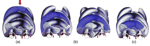
Figure 4‑5. Phases of compression process 61
Centrifugal Compressors
Centrifugal compressors, sometimes termed radial compressors, are a sub-class of dynamic axisymmetric work-absorbing turbomachinery. The idealised compressive dynamic turbo-machine achieves a pressure rise by adding kinetic energy/velocity to a continuous flow of fluid through the rotor or impeller. This kinetic energy is then converted to an increase in potential energy/static pressure by slowing the flow through a diffuser. The pressure rise in the impeller is almost equal to the rise in the diffuser section, in most cases.
In the case of where flow simply passes through a straight pipe to enter a centrifugal compressor; the flow is straight, uniform and has no vorticity. As the flow continues to pass into and through the centrifugal impeller, the impeller forces the flow to spin faster and faster. According to a form of Euler’s fluid dynamics equation, known as the ‘pump and turbine equation’, the energy input to the fluid is proportional to the flow’s local spinning velocity multiplied by the local impeller’s tangential velocity. A simple centrifugal compressor has four components: inlet, impeller/rotor, diffuser and collector. The inlet to a centrifugal compressor is typically a simple pipe. It may include features such as a valve, stationary vanes/air foils (used to help swirl the flow) and both pressure and temperature instrumentation. All of these additional devices have important uses in the control of the centrifugal compressor. The centrifugal impeller is the key component that makes a compressor centrifugal. The impeller contains a rotating set of vanes (or blades) that gradually raises the energy of the working gas. This is identical to an axial compressor with the exception that the gases can reach higher velocities and energy levels through the impeller’s increasing radius.
Scroll Compressors
A scroll compressor (also called spiral compressor), is a device for compressing air or refrigerant. Many residential central HP and A/C systems employ a scroll compressor instead of the more traditional rotary and reciprocating compressors. A scroll compressor uses two interleaving scrolls to pump, compress or pressurise fluids such as liquids and gases. The vane geometry may be involutes, Archimedean spiral or hybrid curves. Often, one of the scrolls is fixed, while the other orbits eccentrically without rotating, thereby trapping and pumping or compressing pockets of fluid between the scrolls. The compression process occurs over approximately two to two and one-half rotations of the crankshaft, compared with one rotation for rotary compressors, and onehalf rotation for reciprocating compressors. The scroll discharge and suction processes occur for a full rotation, compared to less than a half-rotation for the reciprocating suction process, and less than a quarter-rotation for the reciprocating discharge process. Reciprocating compressors have multiple cylinders (typically, anywhere from two to six), while scroll compressors only have one compression element.
Scroll compressors never have a suction valve, but depending on their application may or may not have a discharge valve. The use of a dynamic discharge valve is more prominent in high-pressure ratio applications, typical of refrigeration. The use of a dynamic discharge valve improves scroll compressor efficiency over a wide range of operating conditions, when the operating pressure ratio is well above the built-in pressure ratio of the compressors. The isentropic efficiency of scroll compressors is slightly higher than that of a typical reciprocating compressor when the compressor is designed to operate near one selected rating point. The scroll compressors are more efficient in this case because they do not have a dynamic discharge valve that introduces additional throttling losses. However, the efficiency of a scroll compressor that does not have a discharge valve begins to decrease when compared with the reciprocating compressor at higher-pressure ratio operation. The scroll compression process is nearly 100% volumetrically efficient in pumping the trapped fluid. The suction process creates its own volume, separate from the compression and discharge processes further inside. By comparison, reciprocating compressors leave a small amount of compressed gas in the cylinder, because it is not practical for the piston to touch the head or valve plate. The remnant gas from the last cycle then occupies space intended for suction gas. The reduction in capacity (i.e. volumetric efficiency, λk) depends on the suction and discharge pressures with greater reductions occurring at higher ratios of discharge to suction pressures.
Until recently, a powered scroll compressor could only operate at full capacity. Modulation of the capacity was accomplished outside the scroll set. In order to achieve partial-loads, engineers would bypass refrigerant from intermediate compression pocket back to suction, vary motor speed, or provide multiple compressors and stage them on and off in sequence. Recently, scroll compressors have been manufactured that provide partial-load capacity within a single compressor. These compressors change capacity while running. While scroll compressors can also rely on vapour injection to vary the capacity, their vapour injection operation is not as efficient as that of reciprocating compressors. This inefficiency is caused by the continuously changing volume of the scroll compressor’s compression pocket during the vapour injection process. As the volume is continuously in flux, the pressure within the compression pocket is also continuously changing which adds inefficiency to the vapour injection process. Some of the best compressors with efficiencies of up to 60% of Carnot’s theoretical limit are produced by Danfoss, Copeland, York, Trane, Embraco and Bristol compressor manufacturers.
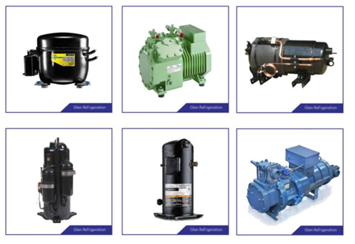
Figure 4‑6. Rotary Screw and reciprocating Compressors
4.3 Lubrication methods and oil management
Lubrication is key to the performance and reliability of high-temperature heat pump systems. The primary function of the oil is to lubricate and protect the compressor. In addition, it also provides cooling of the parts heated by friction, a seal against working medium gas leakage, removes impurities, and reduces the noise produced by the moving parts. To fulfil these tasks the lubricant oil must have the required properties, in particular viscosity, which is temperature and pressure dependent and is impacted by the solubility and miscibility between oil and working medium.
Lubrication of the compressor at high temperatures is one of the critical issues and requires specific demands on the lubricant oils. It is pointed out that the safety limit to avoid oil degradation is 180 °C for most of the commonly used lubrication oils in compressors.
Lubrication is crucial for proper operation of the compressor and for the efficiency and the performance of the heat pump. Lubricant oil is required for the lubrication of the compressor, expansion valve, and other moving parts. It must have the required characteristics, particularly in terms of viscosity, which is temperature and pressure dependent. Additionally, the solubility of the working medium in the oil significantly affects its lubricating properties (viscosity) and heat pump capacity, as the dissolved working medium will remain in the liquid state and will not be available for the thermodynamic cycle. The result is a reduction of the heat pump’s thermal capacity and the Coefficient of Performance (COP). The main function of the oil is to reduce frictional wear of moving surfaces, including bearings and other moving parts of the compressor. In addition, oil also provides cooling of the compressor, removes debris, and provides a seal against working medium gas leakage. The oil also reduces corrosion, deposits, and the noise produced by the moving parts. Poor lubrication can lead to the compressor damage.
- Lubricants for general commercial systems are based on mineral oils, and the following properties are required of the lubricant selected:
- It must be compatible with the refrigerant, i.e. not form any compounds or promote chemical activity.
- The mixture with the refrigerant in the lubrication circuit must provide adequate lubrication of the working parts.
- It must not solidify or throw out any solids such as waxes, within the working range, or clog strainers or driers.
- It must be free of water or other contaminants which will affect the system.
- It must not be prone to foaming.
- It must be resistant to oxidation (high flash-point).
- It must have a low vapour pressure.
- For hermetic and semi-hermetic compressors, it must have a high dielectric strength.
In refrigeration systems, lubrication has crucial role on performance of the system and the selection of the right lubricant for the refrigeration system is very important. The choice of lubricant depends on the system, the refrigerant type and application. The lubricants which are commonly used in refrigeration systems include mineral oil (MO), polyol ester oil (POE), polyalkylene glycols oil (PAG), poly-alfa olefin oil (PAO), alkyl benzene oil (AB), poly222vinyl ether oil (PVE), etc. A lubricant in a refrigeration system plays different roles such as lubricating internal parts of the compressor, contributing in heat removal from compressor, and also sealing and cleaning the system, etc. To investigate the acceptability of the lubricants to be used in the refrigeration systems, the parameters including the miscibility, viscosity, stability and compatibility must be taken into consideration. These factors have important influence on a sufficient lubrication of the refrigeration system. In fact, an improper selection of a lubricant may cause some problems in the refrigeration system. For example, when the viscosity of the lubricant-refrigerant blend is too low, friction and wear may increase due to incomplete or ineffective separation of the metal surfaces. On the other hand, when the viscosity is too high, it may cause a reduction in pumping efficiency due to the obstructed flow. Another example of the inefficient use of lubricant is the oil entrapment which may lead to a poor oil return and consequently oil starvation [2], and also a reduction in the heat exchange effectiveness in the heat exchangers), often, it is possible to add an oil separator after the compressor to decrease the lubricant flow into the heat exchangers. About the miscibility factor, for partly miscible oils and refrigerants, separation in the condenser may occur which could lead to the appearance of a refrigerant-rich phase and an oil-rich phase. In the oil-rich phase, the oil accumulation in the refrigerant reservoir can happen, while the refrigerant-rich phase is carried over to the expansion valve. This may cause a restriction of oil return to the compressor. Also, the problem of wax formation and consequently phase separation should be taken into account when the lubricant is subjected to low temperature in the evaporator. It is also observed that a low solubility of the refrigerant in oil may cause the problem of oil retention to the compressor.
Selecting basestocks. According to the refrigeration industry, mineral oils and synthetic alkylbenzenes were the lubricants of choice in the systems operating with CFCs, HCFCs and hydrocarbons due to their compatibility and miscibility with these lubricants. The regulations and legislative acts adopted by the European Union resulted in the phase-outs of CFC and HCFC refrigerants. Then, the refrigeration industry employed HFCs and later, their low-GWP alternatives, HFOs, in the refrigeration systems. But, for the highly polar HFC and HFO refrigerants, alkylbenzenes and mineral oils lubricants were insufficient due to the low polarity. To solve this problem, POEs and PAGs are proposed as appropriate lubricants for HFCs and HFOs. In refrigeration systems operating with HFCs, the lubricants basestocks are primarily based on POEs and PAGs (POEs as the choice for most stationary systems while PAGs for automotive air conditioning systems). Considering the compatibility of HFOs such as R1234yf with lubricants, POEs are the lubricants of choice, while it is not recommended to use mineral oils in HFO refrigeration systems. Hygroscopic characteristic (the ability of the oil to absorb moisture) of POE and PAG lubricants makes it essential to consider special care in manufacturing, storing and using these oils to avoid chemical reactions in the system such as hydrolysis in POE. For Example, hydrolysis in POE oil causes the decomposition of the oil into partial esters, organic acid and alcohol in the presence of water. Comparing to POE oils, PAGs are more hygroscopic, but this oil does not undergo hydrolysis in the presence of water.
In ammonia refrigeration systems, the lubricant must provide good fluidity at low temperatures and yet still maintain good film thickness at operating temperatures, so a high viscosity index is desirable. When using ammonia in refrigeration systems, most of the oils are not miscible with this refrigerant. In these systems, the use of oil separator is necessary as the miscibility of oil and refrigerant during the liquid phases is not possible. In ammonia refrigeration system, non-soluble/miscible oils are advantageous, so, PAOs and mineral oils are of choice lubricants to use with ammonia, and also alkylated benzene particularly when working at low temperature. PAOs also can be used in blends with mineral oils in ammonia refrigeration systems.
In the refrigeration systems operating with carbon dioxide, extreme mechanical stress on moving parts and bearings are expected due to the much higher service pressures than halogenated refrigerants. CO2 is extremely soluble in oils and consequently remarkable drops in viscosity and breaking down of the oil film are expected. The lubricants of choice for CO2 systems are POE and PAG oils, while the lubricant oils which are not suitable for the refrigeration systems working with CO2 include mineral oil, PAO and alkyl benzene. When using PAGs, the viscosity drop in the system is not as noticeable as the time POEs are used. Reduced viscosity in the case of using POEs may have negative influence on the lubrication in some parts of the compressor specially at start-up. Specially designed POEs for CO2 systems are developed to withstand the high solvency of the CO2 to minimize the improper sealing of clearances and loss of compression caused by inadequate lubrication. It also should be noted that, to avoid the acidification of the oil, the water content in the refrigeration systems operating with CO2 should be controlled to be less than 5 ppm. Hydrocarbons have very low GWP, good material compatibility and excellent thermodynamic properties, but these refrigerants have high flammability (belonged to safety category A3). Mineral oils and POEs are of choice for the refrigeration systems operating with hydrocarbons as these refrigerants have high solubility with mineral and ester oils. At very low temperatures, the lubricants for HC refrigeration systems are required to have a very low pour point (indicating the lowest temperature at which a lubricant is designed to flow) and, also, a very low vapour pressure. For these applications the common choices are PAG and PAO. Table 4‑1 shows how some lubricant chemistries perform with the refrigerants and Table 4‑2 represents the lubricants of choice for some low-GWP (≤750) refrigerants.
Regarding the use of PAG and PVE lubricants it should be noted that PAG oils exhibit relatively low dielectric strength and it makes them to be less suitable for semi-hermetic and hermetic compressors. PVE oils have high dielectric strength and good stability (thermally and chemically), despite the higher hygroscopic character than POEs. PVEs are being increasingly employed as lubricants in compressors for factory-made air conditioners and chillers, and PAG oils are more suitable for mobile air conditioning systems with open drive compressors. In electric vehicle ACs, R1234yf is developed and introduced as electric vehicle industry standard (as low GWP drop-in alternative to R134a). The main concern in using R1234yf is that it is more chemically reactive than R134a, so, the lubricant of choice must have suitable stability properties to neutralize the reactivity behavior of the refrigerant. Other major factors in right selection of the lubricant including the suitable miscibility, compatibility, etc with respect to the refrigerant type should also be taken into account. In this case, PAG oils have the most preferential properties and are the lubricant of choice for electric vehicle ACs.
Table 4‑1. Lubricant Options for Refrigerant Chemistry [4]
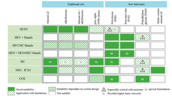
Table 4‑2. Lubricants for some low-GWP refrigerants [5]
| ASHRAE # | GWP | Replaces | Lubricant |
| R1234yf | 1 | R134a | Alkylbenzene, Synthetic (POE, PAG) |
| R1234ze | 1 | R134a | Alkylbenzene, Synthetic (POE, PVE, PAG) |
| R455A | 146 | R404A – R507 | Synthetic (POE) |
| R450A | 547 | R134a – R401A – R401B – R409A | Synthetic (POE) |
| R1233zd | 1 | R123 | Alkylbenzene, Mineral oil, Synthetic (POE, PVE) |
| R466A | 733 | R410A | Synthetic (POE) |
4.4 Compressor performance metrics and influencing factors
To reduce the energy usage of the vapor compression cycle, one effective strategy involves minimizing the energy consumption of the compressor while maintaining the required compression ratio. In simpler terms, enhancing the compressor’s performance is the goal. In recent times, a significant advancement in compressor technology has been the development of the scroll compressor, which is roughly 10% more efficient than the conventional reciprocating compressor. This improvement can be attributed to three main factors.
Firstly, in the scroll compressor, the suction and discharge processes are isolated, preventing the introduction of heat into the suction gas as it enters the compressor. This is in contrast with reciprocating compressors, where heat is added.
Secondly, the compression process in the scroll compressor occurs gradually over 540 degrees of rotation, as opposed to the 180-degree rotation in reciprocating compressors. Consequently, torque fluctuations are only about 10% of what is experienced in reciprocating compressors.
Thirdly, the scroll compression mechanism allows for the elimination of suction and discharge valves, which are sources of pressure losses in reciprocating compressors.
Additionally, scroll compressors offer improved reliability due to their fewer moving parts and their ability to operate more effectively under liquid slugging conditions. Recent studies combining heat pumps with scroll compressors have demonstrated the energy efficiency benefits of such integration.
4.5 Compressor control strategies and regulation methods
The use of inverter technology makes it possible to ensure high efficiency of heat pumps with spiral compressors in the entire power range. A combination of two “tandem compressors” compressors is used for the manufacture of heat pumps of medium and higher power. Such systems guarantee high efficiency when the heat load changes, which allows optimal adaptation to different operating conditions.
The introduction of AC variable frequency drive technology, allows Refrigeration machine builders and system integrators to vary the cooling capacity of the compressor by changing the compressor speed, to accurately maintain the cooling requirement. This is achieved by fitting a pressure transducer into the low- pressure suction line. The transducer measures the suction pressure and the controller compares the actual pressure to the required set-point. The controller subsequently adjusts the compressor’s speed to run faster or slower.
Most compressor motors are designed for 50Hz or 60Hz supplies. The compressor capacity increases proportionally to output speed. Therefore, setting output frequency to 60Hz, the cooling capacity is increased by 20%. If the compressor being controlled by the variable frequency drive is on the lead compressor, on a multi-compressor refrigeration rack system, it is possible to increase the output speed of the compressor beyond 60Hz. Semi hermetic compressors, can run safely at output speeds of 65Hz to 70Hz, providing 30% – 40% free cooling capacity. The maximum & minimum output speed should always be confirmed by contacting the compressor manufacturer. Increasing the output speed, and thereby the cooling capacity, could result in the second fixed speed compressor on the rack, operating less often. This results in lower energy costs, improved system control, and extended compressor life, due to fewer starting cycles.
Digital scroll capacity control
In this method, scrolls force to separate and compression of refrigerant stops. This modulates refrigerant flow without changing or stopping the compressor motor. The separation of the scrolls is realized by using an external solenoid valve; also, there is a bypass connection line between the discharge chamber and the intake gas. The upper scrolls can separate from the bottom scroll by 1 mm vertically. A piston is fixed to the top of the upper scroll and lifts up the upper scroll when it moves up. There is a modulation chamber at the top of the piston that is connected to the discharge pressure through a bleed hole. An external solenoid valve connects the modulation chamber with the suction side pressure. If the solenoid valve is closed, the scrolls operate as a classical scroll compressor. If the solenoid is opened, the discharge chamber and intake gas pressure connect each other and decrease the discharge pressure. This leads to less pressure holding the piston down, thereby causing the piston to shift upward, which in turn lifts the upper scroll. This action separates the scrolls and results in no mass flow through the scrolls. De-energized external solenoid valve again loads the compressor fully, and the compression is resumed (Figure 4‑7).
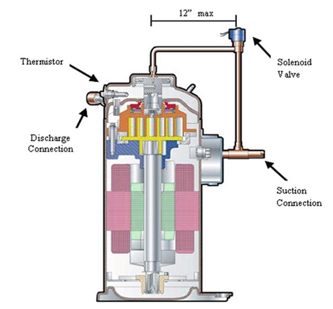
Figure 4‑7. Digital scroll piping capacity control [6]
During the loaded state, the compressor operates like a standard scroll and delivers full capacity and mass flow. However, during the unloaded state, there is no capacity and no mass flow through the compressor. The scrolls are separated in a periodic cycle (20 seconds) to obtain a time-averaged compressor capacity based on the ratio of loading and unloading times. This allows the digital scroll to achieve infinite capacity modulation between 10 and 100%. For example, 20-second cycle and the solenoid are de-energized for 16 seconds and then energized for 4 seconds; the resulting capacity will be 80%. This method provides very wide capacity range with continuous modulation, high efficiency, and very tight temperature control. But higher initial cost is the disadvantage of these methods compared to hot gas bypass method. Also, variable speed and digital scroll capacity controls are compared, and they give very close capacity modulation results.
Cylinder unloading capacity control
Capacity control also can be occurred through reciprocating compressor’s cylinder unloading. The cylinder unloading capacity control method (suction valve unloading method) works by lifting the suction valves of some cylinders to the open position. A thermostat (or pressure transducer) energizes a solenoid (or solenoids if there are multiple cylinders in the compressor) that forces the suction valve to stay open. The gas cannot be compressed within the open cylinders, which results a drop in refrigeration capacity. To prevent overheating of the compressor, a thermostatic expansion valve should be installed to provide cooling to the compressor suction gas. This capacity reduction is then followed by hot gas bypass. Their construction is relatively low in cost, but they usually require a multicylinder compressor. The achievable capacity graduations depend on the constructional design. With 4-, 6-, and 8-cylinder compressors, it is usual to operate two cylinders per load stage, which permits graduations of (25)–50–(75)–100% or 33–66–100%.
Hot gas bypass capacity control
Hot gas bypass is a method that modulates refrigerant flow by bypassing some of the high-pressure refrigerant gas (hot gas) discharged from the compressor back to the suction line without going through the evaporator, and the gas does any cooling. The capacity of reciprocating and centrifugal compressors can also be controlled by this method. Some applications use two or more methods for smoother switching and better control such as unloading in conjunction with hot gas bypass. Extra valves and piping are required for this capacity control, and capacity can be quickly adjusted by opening or closing a valve, but the number of capacity steps is finite. It may not prove precise and smooth temperature control. Suction pressures below the compressor designed limit are prevented because low suction densities result in poor compressor cooling. Therefore, hot gas bypasses into the systems’ low pressure side.
Slide valve capacity control
The slider control allows an adaptation of the compressor displacement to the power requirement by shifting the start of the compression process through an axial slide of the control slider. At the same time, the outlet window is adapted to the newly developing displacement in this series. Rotary-screw compressors use slide valves to adjust the necessary refrigeration capacity at partial loads by permitting the equipment to reduce the total volume of refrigerant compressed within the housing. The slide valve modulates compressor capacity between 25% to 100% range by 25% steps. The most common capacity control methods are capacity control slide valve for screw compressor. As the volume of refrigerant vapor to undergo compression is reduced, the compressor’s capacity is reduced, and the effective volume ratio of the compressor also decreases.
Multiple compressor capacity control
Refrigeration system capacity can be modulated by using multiple refrigeration circuits or by using multiple compressors in single-circuit systems. Under partial load conditions, the compressors may be cycled in and out of service as required as well as providing a level of redundancy in the event one of the compressors should fail. Oil equalization is needed for these kinds of compressors. One of the least expensive forms of modulation, reliability, can be seen as advantages of the multiple compressor capacity control. On the other hand, multiple compressor capacity provides finite number of capacity steps and limited efficiency gains, to obtainable, because of the capacity modulation step.
Variable speed capacity control
Variable speed control can be realized in different ways to regulate the speed of the compressor motor such as electronic variable frequency drives. Variable frequency drives (VFD) are also known as adjustable-frequency drives (AFD), variable speed drives (VSD), AC drives, micro-drives, or inverter drives. Compressor rotational speed can be varied to match the system’s changing requirement for refrigeration capacity of a variable speed drive.
4.6 Review Questions
- Explain the thermodynamic role of the compressor in a vapour compression cycle. How does it enable phase change and energy transfer within the system?
- Compare the operating principles of reciprocating, scroll, and screw compressors. Discuss which types are best suited for small, medium, and large-capacity heat pump systems, and why.
- Differentiate between hermetic, semi-hermetic, and open compressors. What are the main advantages and disadvantages of each design in terms of maintenance, cooling, and leakage risk?
- The compression process in a real system is irreversible. Identify the causes of this irreversibility and explain how it affects compressor performance and overall system COP.
- Discuss the main functions of lubricating oil in compressor operation. What properties must a lubricant have to ensure reliability and efficiency in high-temperature heat pumps?
- Explain the importance of matching compressor type and lubricant to the selected refrigerant. Use examples of refrigerant–oil compatibility issues that could affect performance or system life.
- Modern heat pumps often use inverter-driven scroll compressors. Explain how variable-speed control improves system efficiency under partial load conditions.
- Describe at least two compressor capacity control methods (e.g., digital scroll control, cylinder unloading, or slide valve modulation). Compare their advantages in terms of response, energy efficiency, and cost.