Lesson 6.Refrigeration Circuit Components III: Expansion Devices
February 9, 2026Lesson 9.Standard Compression Cycle
February 9, 2026Welcome to this lesson! Start by watching a recap video of this lesson.
Click on the gear icon to choose subtitles of your preferred language.
7.1 Four-way reversing valve (heating «-» cooling)
The four-way reversing valve is a fundamental component in modern heat pump systems, enabling the reversible operation required to switch between heating and cooling modes. By controlling the direction of refrigerant flow, it allows the evaporator and condenser to alternate functions depending on whether the system is in heating or cooling mode[1].
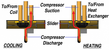
Figure 7‑1. Four-Way Reversing Valve in Heat Pump [2]
Structurally, the valve typically consists of four ports and an internally sliding element actuated by a solenoid pilot valve, which shifts position to reverse the refrigerant cycle efficiently and reliably. One of the ports usually connects to the suction line, while the other three connect to the compressor, condenser, and evaporator, respectively. The internal mechanism is precisely engineered to handle pressure variations during mode switching[3].
By reversing the refrigeration cycle, the four-way valve enables heat pumps to provide year-round climate control. In cooling mode, the system absorbs heat indoors and rejects it outdoors; in heating mode, this process is reversed-extracting heat from the outdoor environment and delivering it indoors. The switching process is controlled by energizing or de-energizing the solenoid coil, which moves the sliding element to redirect refrigerant flow paths.
However, conventional four-way valves are not without inefficiencies. Research has identified issues such as pressure drops caused by internal bends and friction, unwanted heat transfer between hot and cold streams, and refrigerant leakage through valve clearances. Innovative valve designs have demonstrated that reducing these losses can decrease pressure drop by up to 60%, directly improving the system’s COP. Minimizing leakage between high- and low-pressure sides further enhances overall energy efficiency.
The quick and reliable switching capability of four-way valves is essential for maintaining high system performance. It ensures seamless transitions between operational modes without excessive wear or performance degradation, which is particularly important in climates with distinct heating and cooling seasons[4].
The four-way reversing valve is a key enabling technology for dual-mode heat pump operation. Ongoing design improvements are focused on reducing pressure losses, minimizing internal leakage, and enhancing reliability, all of which contribute to higher energy efficiency and system longevity.
7.2 Solenoid valves
Solenoid valves and check valves are essential components in heat pump refrigeration circuits. These devices manage refrigerant flow, enhance system efficiency, and provide critical protections against operational faults. As heat pumps advance technologically, the role of these valves has become even more vital in maintaining optimal performance [5],[6].
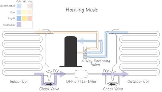
Figure 7‑2. Schematic of a Heat Pump Refrigeration Cycle [7]
The incorporation of solenoid and check valves extends beyond flow control, contributing to automated functionality and energy optimization. These components enable precise refrigerant flow management, prevent refrigerant migration during system shutdown, support hot gas bypass operations, and manage defrost cycles effectively. Their role in enhancing heat pump reliability and energy efficiency is crucial, especially as systems become more complex. The HVAC-R solenoid valve market reflects this growing importance, with a valuation of approximately €2.25 billion in 2024 and projections reaching €3.69 billion by 2033, growing at a Compound Annual Growth Rate (CAGR) of 6.2% [8].
Technical Construction and Operating Principles: Solenoid valves control refrigerant flow using electromagnetic coils, operating via direct or pilot-actuated mechanisms. Direct-acting solenoids use magnetic force to open the valve, while pilot-operated variants utilize system pressure to assist movement, allowing control in high-pressure systems (Figure 7‑3).
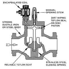
Figure 7‑3. Cross-sectional diagram of a solenoid valve, relevant for refrigeration and heat pump applications
Liquid Line Applications: Solenoid valves are commonly installed between the condenser and expansion device to prevent refrigerant migration and enable pump-down control [9].
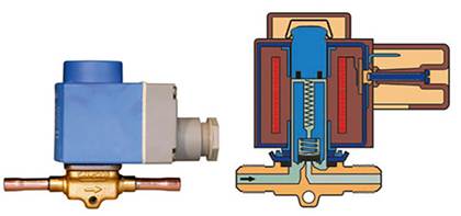
Figure 7‑4. Solenoid valve for refrigeration heat pump systems: external view and detailed cross-sectional diagram [10]
Hot Gas Bypass Control: These valves manage compressor discharge gas during low load conditions to prevent coil freezing.
Defrost Cycle Management: Solenoids direct hot gas to evaporator coils during defrost, efficiently removing frost accumulation [11].
Modern valves must accommodate refrigerants such as R410A, R134a, and R1234yf, with pressures from 3.0 MPa to 4.2 MPa. Electrical ratings vary (24V to 240V), and insulation ratings ensure performance in extreme environments.
7.3 Check Valves
Check valves prevent backflow and pressure surges:
- Ball Check Valves: Self-cleaning, multi-orientation installation.
- Piston Check Valves: Precision-guided for tight sealing.
- Swing Check Valves: Hinged disc design with low pressure drop, ideal for horizontal lines [12].
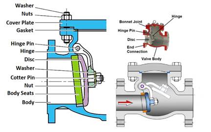
Figure 7‑5 Detailed diagrams of check valve internal parts and construction showing components like hinge, disc, and body
for technical understanding [13]
Installation Considerations
Proper flow alignment is essential to ensure that the check valve operates as intended, minimizing turbulence and preventing premature wear or valve fluttering. To achieve stable flow conditions, it is recommended to install check valves with a straight pipe run of at least five pipe diameters upstream and downstream of any fittings such as elbows, tees, or reducers. This spacing helps to reduce flow disturbances that can interfere with valve sealing and response time. Additionally, in specialized applications such as transcritical CO₂ refrigeration systems – where operating pressures are significantly higher than in conventional systems – check valves must be selected to withstand working pressures of up to 140 bar. These high-pressure-rated valves are engineered with robust materials and sealing designs to ensure safe and reliable operation under extreme pressure and temperature fluctuations [14].
Failure Modes and Troubleshooting
Solenoid Valves:
- Coil Burnout: Overheating due to electrical faults;
- Mechanical Failure: Caused by debris or wear in the plunger assembly;
- Electrical Faults: Include wiring issues and fluctuating resistance.
Check Valves:
- Disc Fluttering: Occurs when valves are improperly sized;
- Water Hammer: Controlled using spring-assisted valves to dampen flow reversals [15],[16].
Installation and Maintenance
Solenoid Valves: Correct wiring, proper mounting, and accurate brazing techniques are vital. Coil orientation must be upright, and system refrigerant flow must match valve direction.
Check Valves: Positioning and flow stabilization using adequate straight pipe runs prevent valve malfunction. Orientation-specific designs (e.g., swing check valves) must be installed accordingly 83.
Regulatory Standards
Modern solenoid and check valves must comply with various safety and performance standards. AHRI Standard 760-2014 establishes performance rating requirements for solenoid valves used with volatile refrigerants, including test procedures and minimum data requirements 77.
UL 60335-2-89 requirements for A2L refrigerant systems mandate specific safety shut-off valve characteristics, including tight sealing capabilities with minimal pressure drop. These standards ensure system safety while accommodating emerging refrigerant technologies [17].
Environmental Regulations drive adoption of valves compatible with low-GWP refrigerants and energy-efficient operation. Compliance with environmental standards becomes increasingly important as regulations evolve toward sustainability objectives [18].
7.4 Filter-driers and sight glasses
Filter-driers and sight glasses are essential components in heat pump refrigeration circuits. They ensure system reliability, efficiency, and longevity by removing contaminants and providing visual feedback on refrigerant condition. This review covers their construction, function, technical aspects, and current industry trends, with a focus on applications in modern heat pump systems.
7.4.1 Filter-Driers
Function and Importance: A filter-drier serves two main purposes: removing moisture and acids from the refrigerant and filtering out solid contaminants such as metal particles or debris. Moisture and acids can lead to corrosion, oil degradation, and eventual compressor failure, while particulates may clog metering devices and reduce system performance [19].
Construction: Filter-driers typically use a sealed steel shell capable of withstanding pressures up to 46–47 bar, and a solid or replaceable desiccant core made of approximately 80% molecular sieve and 20% activated alumina, which together adsorb both moisture and acid. Internal mesh screens capture solid particles down to 20–25 microns 91, [20].
Common types include:
- Solid-core liquid-line driers for one-way flow in standard systems.
- Bi-flow driers for reversing valve systems like heat pumps, designed with screens and desiccant beds on both ends to support flow in either direction;
- Burnout suction-line driers for acid removal after compressor failures, often with added activated carbon;
- Replaceable-core driers, used in large or commercial applications, which allow core replacement without opening the sealed refrigeration lines.
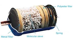
Figure 7‑6. Parts of a bi-flow filter-drier [21]
Proper sizing of filter-driers is critical to ensure reliable system operation, as an undersized drier can lead to excessive pressure drop, which reduces overall efficiency and may impair refrigerant flow to the expansion device. To maintain optimal performance, the pressure drop across the drier should typically remain below 0.2 bar. In addition to sizing, correct placement is equally important and depends on both the system configuration and the type of drier. In conventional air conditioning and refrigeration systems, filter-driers are commonly installed in the liquid line between the condenser and the expansion valve, where they effectively capture moisture and debris before the refrigerant enters the metering device. For heat pump systems, bi-flow filter-driers are used to accommodate refrigerant flow reversal between heating and cooling modes; these are specifically designed with symmetrical internal construction to ensure consistent performance in both directions. In the case of a compressor burnout, a burnout suction-line drier is temporarily installed in the suction line to remove acidic residues, carbon particles, and other contaminants from the system. Furthermore, all filter-driers must be compatible with the specific refrigerants and lubricants used in the system, including HFCs (e.g., R134a, R410A), HFOs (e.g., R1234yf), hydrocarbons (e.g., R290), natural refrigerants like CO₂ (R744), and lubricants such as POE (polyolester) and PAG (polyalkylene glycol) oils. Selecting a filter-drier that is correctly sized, properly placed, and chemically compatible with the system’s working fluids is essential for long-term reliability, moisture and acid control, and optimal heat pump performance.
7.4.2 Sight Glasses
Sight glasses provide a visual inspection point in the liquid line, enabling technicians to monitor the refrigerant’s physical state. These devices help identify refrigerant undercharge (visible bubbles), system moisture (through chemical indicators), and contaminant flow or oil migration91,[22] (Figure 7‑7).
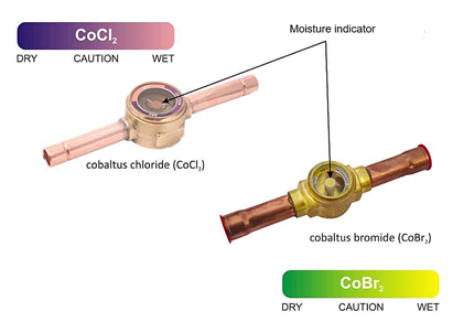
Figure 7‑7. Sight glass with moisture indicator [23]
Modern sight glasses are critical diagnostic tools in heat pump and refrigeration systems, providing a simple yet highly effective means of visually assessing the condition of the refrigerant. One of their most valuable features is the integrated colour-changing moisture indicator, which allows technicians to detect the presence of moisture within the system immediately. These indicators are typically chemical based, shifting colour (e.g., from green to yellow) when moisture levels exceed acceptable thresholds, thereby alerting technicians to potential issues such as refrigerant contamination, insufficient dehydration, or drier saturation. For accurate observation, sight glasses are strategically placed after the filter-drier and just before the expansion device, a location where refrigerant is in subcooled liquid form and any phase instability—such as the presence of bubbles or flash gas—is most clearly visible. This placement ensures that both moisture levels and refrigerant charge condition can be evaluated before the refrigerant undergoes throttling into the evaporator. Given the high operating pressures of many modern refrigerants, it is essential that sight glasses be pressure-rated to match or exceed the system’s maximum working pressure. This is particularly important in systems using high-pressure refrigerants like R410A, which operates around 4.2 MPa (42 bar), and R744 (CO₂), which in transcritical systems can exceed 10 MPa (100 bar) during normal operation [24]. Using improperly rated components in these systems can lead to mechanical failure and safety hazards.
In response to the growing demand for compact and service-friendly installations, many manufacturers now offer integrated units that combine the filter-drier and sight glass into a single component. These assemblies reduce the number of joints and fittings in the system, thereby minimizing potential leak points and simplifying both installation and routine maintenance tasks.
In parallel, the technology behind moisture indicators has also evolved. Modern indicators are more chemically stable and calibrated to respond accurately to a wider range of refrigerant blends and synthetic oils, including polyester (POE) and polyalkylene glycol (PAG) lubricants. These enhanced indicators are particularly beneficial in systems using low-GWP refrigerants or blends with differing hygroscopic properties, where traditional indicators may produce misleading readings or degrade over time.
Together, these improvements make sight glasses not only essential for routine service but also an important component in achieving the overall efficiency, safety, and reliability of heat pump and refrigeration systems.
Maintenance
Filter-driers should be replaced whenever the system is opened for service, following compressor burnouts, or if pressure drop across the unit becomes excessive. Sight glasses should be routinely checked for bubbles or indicator colour changes as part of preventive maintenance. Correct sizing, material compatibility, and proper placement of both components are essential to ensure efficient and reliable system operation 91, 95.
7.5 Oil separators and liquid receivers
Oil separators and liquid receivers are critical elements in modern heat pump circuits, supporting both operational reliability and energy efficiency. Their functions, technical design, and integration have evolved in response to advances in refrigerant technology, increased system pressures, and heightened demands for system monitoring and flexibility.
7.5.1 Oil Separators
The oil separator is typically installed immediately after the compressor in the discharge line, where it intercepts oil-laden refrigerant vapor. Its main objective is to mechanically separate entrained oil from the refrigerant, ensuring that the oil is promptly redirected to the compressor crankcase through a dedicated oil return line. This separation process often uses centrifugal or helical mechanisms: the high-velocity gas stream rotates within the separator chamber, forcing oil droplets outward against the vessel walls, where they coalesce and settle. A float valve or needle valve at the base of the separator then returns the oil to the compressor sump, ensuring lubrication and minimizing oil migration risks [25],[26],[27].
In large-scale commercial systems-such as multi-compressor racks-oil separators are often paired with oil reservoirs and regulators to maintain balanced oil levels across all compressors, preventing both overfilling and oil starvation under varying load conditions 98,[28].
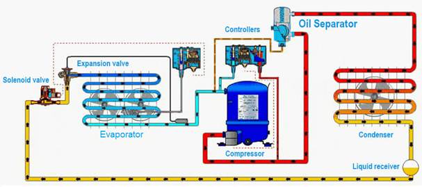
Figure 7‑8. Oil separator place in principle diagram [29]
Contemporary designs accommodate high-pressure refrigerants such as R410A, R32, and CO₂, with working pressure ratings up to 140 bar. To withstand harsh conditions, manufacturers use corrosion-resistant materials and modular construction, facilitating both durability and ease of maintenance. Some models are now integrated with electronic sensors, enabling remote level monitoring, predictive maintenance, and compatibility with cloud-based service platforms 100,[30].
7.5.2 Liquid Receivers
Liquid receivers are located on the high-pressure side of the refrigeration circuit, downstream of the condenser and upstream of the expansion device. Their main purpose is to act as a reservoir for liquid refrigerant, ensuring that a stable, bubble-free supply is available to the metering device—even as system loads or ambient temperatures fluctuate 99,[31].
By temporarily storing refrigerant during low-load conditions and releasing it during peak demand, the receiver helps prevent liquid slugging, ensures a steady refrigerant flow, and supports proper superheat control at the evaporator. Receivers come in vertical and horizontal configurations, are carefully sized to match the system’s expected refrigerant volume swings, and are typically pressure-rated for 45 bar or more depending on the refrigerant used. Many models include service valves, pressure relief valves, and sight glasses for refrigerant level monitoring, all of which simplify charging and maintenance procedures.
System Integration and Trends
Correct sizing and integration of both oil separators and liquid receivers are critical for ensuring the overall performance, reliability, and longevity of heat pump refrigeration systems. An undersized oil separator may fail to capture and return sufficient lubricant to the compressor crankcase, leading to inadequate lubrication, increased mechanical wear, and ultimately premature compressor failure. Similarly, a liquid receiver that is too small may not be able to accommodate refrigerant volume fluctuations during load changes, resulting in refrigerant starvation, unstable evaporator feeding, and potential control instability during peak demand conditions. To address these challenges, modern heat pump designs emphasize smart monitoring, automated diagnostics, and data-driven control strategies. Both oil separators and liquid receivers are now available in advanced configurations that feature:
- Electronic level indicators for real-time tracking of oil or refrigerant volumes;
- Digital pressure and temperature sensors to validate component function and detect abnormal trends;
- Remote alarms and service interface ports that connect to Building Management Systems (BMS), HVAC service platforms, or mobile diagnostic tools.
These smart components not only reduce the need for manual inspection but also support predictive maintenance, allowing system operators to intervene before performance degrades or component failure occurs. Alerts can be configured based on set thresholds or behaviour deviations, enabling automated scheduling of maintenance or technician dispatches with specific troubleshooting guidance.
In essence, the trend in modern refrigeration and heat pump systems is shifting from reactive service models toward proactive, intelligent system management, where devices like oil separators and liquid receivers no longer function as passive components but instead play an active role in system optimization and lifecycle management 100,103.
7.6 Pressure sensors and safety switches
Pressure sensors and safety switches are essential components in modern heat pump systems, ensuring safe, efficient, and reliable operation. These devices monitor system pressures, relay information to control systems, and provide protective measures to prevent damage from abnormal pressure conditions, such as overpressure, vacuum, or refrigerant loss [32],[33].
Pressure Sensors
Pressure sensors (or transducers) continuously measure refrigerant pressure and convert it into an electrical signal that is processed by the controller to regulate operation. Modern electronic pressure sensors offer high precision, rapid response time, and the ability to integrate seamlessly with digital controllers. Many also support programmable features such as normally open/closed contacts or window switching functions. There are two main sensor types:
- Mechanical sensors that use bellows or diaphragms for actuation;
- Electronic sensors that rely on piezoresistive or capacitive sensing elements for more accurate digital feedback [34].
Key applications include monitoring of suction and discharge pressures, activation of variable-speed compressors, and enabling pressure-driven control strategies in advanced heat pump systems 106. Technical features of advanced models include:
- High burst pressure ratings, often up to 42 MPa, particularly for CO₂ (R744) systems;
- Digital signal outputs compatible with building automation;
- Customizable setpoints and diagnostic feedback for predictive maintenance [35].
Safety Switches: Function and Technical Aspects
Safety switches act as critical shut-off devices in heat pump circuits, designed to interrupt compressor operation or signal an alarm when the system operates outside safe limits. These include high-pressure cut-outs, low-pressure cut-outs, and differential switches.
Mechanical safety switches use a direct pressure-sensitive element to activate or break an electrical circuit. These are common in robust or legacy systems 106.
Electronic safety switches, in contrast, use embedded sensors and logic for more precise operation, with options for digital communication and adjustable thresholds 108.
Differential pressure switches monitor pressure differences between two points, such as across a filter or heat exchanger, to detect blockages or flow issues.
Industry Trends
Integration & Digitalization: There is a growing trend toward digital pressure switches and sensors with modbus or CANopen outputs, enabling real-time data transfer to building management systems (BMS).
High-Pressure Compatibility: Newer models are engineered for refrigerants like R744, featuring burst ratings exceeding 40 MPa.
Safety Compliance: Devices are increasingly certified under SIL 3, PLe, and Cat 4, offering redundant outputs, IP65 to IP69K protection, and built-in diagnostics for maximum system safety 105.
Best Practices
To ensure optimal safety, accuracy, and performance, the following installation and operational practices are strongly recommended when working with pressure sensors and switches:
Correct Placement
Strategic placement of pressure sensors and switches is essential for accurate data collection and system protection. Ideal sensor locations include:
- Suction line – monitor evaporator and compressor inlet pressure;
- Discharge line – for high-pressure monitoring and compressor protection;
- Liquid line: to verify condenser and subcooling performance;
- Across filters or heat exchangers – for differential pressure monitoring.
Sensors should be installed perpendicular to the flow path when possible, and away from vibration zones, with dampers or isolation fittings if necessary to reduce mechanical wear and noise interference.
Routine Testing
Even the most robust mechanical and electronic safety switches can drift over time or fail due to wear, contamination, or electrical faults. Best practice includes:
- Scheduled testing or calibration checks (annually or per OEM guidelines).
- Simulation of pressure conditions to verify correct switch activation.
- Visual inspections for corrosion, cracked housings, or broken seals.
Routine functional testing is especially critical in safety-critical systems, such as those using flammable refrigerants or operating under high pressures.
Appropriate Setpoint Selection
Incorrect setpoint selection can lead to false trips or, conversely, failure to protect equipment. Setpoints must be selected based on:
- Manufacturer’s operating pressure envelope;
- Refrigerant characteristics (vapor pressure curve, critical point);
- Expected ambient temperature ranges;
- Compressor tolerances and operating pressure limits.
In programmable electronic switches, multiple setpoints or hysteresis windows can be configured for multi-stage protection, alarm triggering, or compressor staging based on load demand. These components often feature:
- Thick-walled stainless-steel diaphragms or pressure ports;
- Hermetically sealed electronics to avoid failure under thermal and mechanical stress;
- Compliance with pressure equipment directives (PED) and regional safety codes.
Safety Compliance
To meet stringent operational and workplace safety standards, pressure switches and sensors are increasingly certified to internationally recognized levels of functional safety. These include:
- SIL 2 and SIL 3 (per IEC 61508 / IEC 61511) – denoting low probability of failure in safety-related applications;
- Performance Level e (PLe) and Category 4 (per ISO 13849) – required in safety-critical mechanical systems;
- Environmental protection ratings such as IP65, IP67, IP68, and IP69K, indicating full protection from water, dust, and high-pressure cleaning operations.
High-compliance devices also include:
- Redundant output channels for fail-safe operation;
- Self-diagnostic circuitry and error status reporting;
- Overvoltage and short-circuit protection for harsh industrial environments.
These certifications and features are crucial for pressure control devices used in safety circuits, such as high-pressure cut-outs that protect the compressor or system components from catastrophic failure.
7.7 Review Questions
- Explain the function of the four-way reversing valve in a heat pump system. How does it enable the unit to operate in both heating and cooling modes?
- Describe the operational difference between a solenoid valve and a check valve. In which parts of a heat pump circuit are these valves typically used?
- State the purpose of a filter-drier and a sight glass in a refrigeration circuit. How do they contribute to system reliability and maintenance?
- Why does internal leakage or pressure drop within a four-way valve reduce the COP of a heat pump?
- Explain how a bi-flow filter-drier differs from a standard liquid-line drier and why it is necessary in reversible heat pump systems.
- A heat pump system shows moisture discoloration in the sight glass. What does this indicate, and what corrective actions should a technician take?
Oil separators and liquid receivers both store and manage fluids in the system. Compare their roles and explain how incorrect sizing of either component could affect system stability and compressor performance.